Cirkit Designer Logo
Cirkit Designer
Your all-in-one circuit design IDE
Home / 
Component Documentation

How to Use RXB12 RF Receiver: Examples, Pinouts, and Specs

Image of RXB12 RF Receiver
Cirkit Designer LogoDesign with RXB12 RF Receiver in Cirkit Designer

Introduction

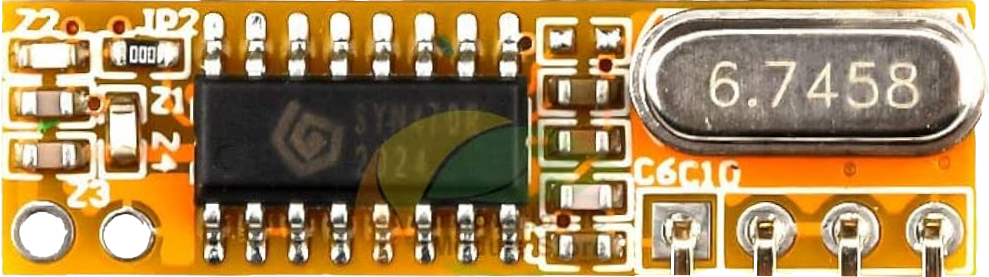
The RXB12 is a compact RF receiver module designed for receiving radio frequency signals in the 433 MHz band. It is widely used in remote control systems, wireless data transmission, and other communication applications. With its high sensitivity and low power consumption, the RXB12 is particularly suitable for battery-operated devices and systems requiring reliable wireless communication.

Explore Projects Built with RXB12 RF Receiver

Use Cirkit Designer to design, explore, and prototype these projects online. Some projects support real-time simulation. Click "Open Project" to start designing instantly!
Arduino UNO with 433MHz RF Module for Wireless Communication
Image of Receiver: A project utilizing RXB12 RF Receiver in a practical application
This circuit consists of an Arduino UNO connected to an RXN433MHz radio frequency module. The Arduino provides 5V power and ground to the RF module and is configured to communicate with it via digital pin D11. Additionally, a multimeter is connected with alligator clip cables to measure the voltage supplied to the RF module.
Cirkit Designer LogoOpen Project in Cirkit Designer
ESP32-Based RF Communication System with 433 MHz Modules
Image of 433 mhz: A project utilizing RXB12 RF Receiver in a practical application
This circuit comprises an ESP32 microcontroller connected to a 433 MHz RF transmitter and receiver pair. The ESP32 is programmed to receive and decode RF signals through the receiver module, as well as send RF signals via the transmitter module. Additionally, the ESP32 can communicate with a Bluetooth device to exchange commands and data, and it uses an LED for status indication.
Cirkit Designer LogoOpen Project in Cirkit Designer
Battery-Powered nRF52840 and HT-RA62 Communication Module
Image of NRF52840+HT-RA62: A project utilizing RXB12 RF Receiver in a practical application
This circuit is a wireless communication system powered by a 18650 Li-ion battery, featuring an nRF52840 ProMicro microcontroller and an HT-RA62 transceiver module. The nRF52840 handles the control logic and interfaces with the HT-RA62 for data transmission, while the battery provides the necessary power for the entire setup.
Cirkit Designer LogoOpen Project in Cirkit Designer
Satellite-Based Timing and Navigation System with SDR and Atomic Clock Synchronization
Image of GPS 시스템 측정 구성도_Confirm: A project utilizing RXB12 RF Receiver in a practical application
This circuit appears to be a complex system involving power supply management, GPS and timing synchronization, and data communication. It includes a SI-TEX G1 Satellite Compass for GPS data, an XHTF1021 Atomic Rubidium Clock for precise timing, and Ettus USRP B200 units for software-defined radio communication. Power is supplied through various SMPS units and distributed via terminal blocks and DC jacks. Data communication is facilitated by Beelink MINI S12 N95 computers, RS232 splitters, and a 1000BASE-T Media Converter for network connectivity. RF Directional Couplers are used to interface antennas with the USRP units, and the entire system is likely contained within cases for protection and organization.
Cirkit Designer LogoOpen Project in Cirkit Designer

Explore Projects Built with RXB12 RF Receiver

Use Cirkit Designer to design, explore, and prototype these projects online. Some projects support real-time simulation. Click "Open Project" to start designing instantly!
Image of Receiver: A project utilizing RXB12 RF Receiver in a practical application
Arduino UNO with 433MHz RF Module for Wireless Communication
This circuit consists of an Arduino UNO connected to an RXN433MHz radio frequency module. The Arduino provides 5V power and ground to the RF module and is configured to communicate with it via digital pin D11. Additionally, a multimeter is connected with alligator clip cables to measure the voltage supplied to the RF module.
Cirkit Designer LogoOpen Project in Cirkit Designer
Image of 433 mhz: A project utilizing RXB12 RF Receiver in a practical application
ESP32-Based RF Communication System with 433 MHz Modules
This circuit comprises an ESP32 microcontroller connected to a 433 MHz RF transmitter and receiver pair. The ESP32 is programmed to receive and decode RF signals through the receiver module, as well as send RF signals via the transmitter module. Additionally, the ESP32 can communicate with a Bluetooth device to exchange commands and data, and it uses an LED for status indication.
Cirkit Designer LogoOpen Project in Cirkit Designer
Image of NRF52840+HT-RA62: A project utilizing RXB12 RF Receiver in a practical application
Battery-Powered nRF52840 and HT-RA62 Communication Module
This circuit is a wireless communication system powered by a 18650 Li-ion battery, featuring an nRF52840 ProMicro microcontroller and an HT-RA62 transceiver module. The nRF52840 handles the control logic and interfaces with the HT-RA62 for data transmission, while the battery provides the necessary power for the entire setup.
Cirkit Designer LogoOpen Project in Cirkit Designer
Image of GPS 시스템 측정 구성도_Confirm: A project utilizing RXB12 RF Receiver in a practical application
Satellite-Based Timing and Navigation System with SDR and Atomic Clock Synchronization
This circuit appears to be a complex system involving power supply management, GPS and timing synchronization, and data communication. It includes a SI-TEX G1 Satellite Compass for GPS data, an XHTF1021 Atomic Rubidium Clock for precise timing, and Ettus USRP B200 units for software-defined radio communication. Power is supplied through various SMPS units and distributed via terminal blocks and DC jacks. Data communication is facilitated by Beelink MINI S12 N95 computers, RS232 splitters, and a 1000BASE-T Media Converter for network connectivity. RF Directional Couplers are used to interface antennas with the USRP units, and the entire system is likely contained within cases for protection and organization.
Cirkit Designer LogoOpen Project in Cirkit Designer

Common Applications

  • Remote control systems (e.g., garage doors, home automation)
  • Wireless data transmission
  • Internet of Things (IoT) devices
  • Alarm and security systems
  • Wireless sensor networks

Technical Specifications

Key Technical Details

Parameter Value
Operating Frequency 433 MHz
Operating Voltage 3.3V to 5.5V
Current Consumption ≤ 5.5 mA
Sensitivity -110 dBm
Modulation Type ASK/OOK
Data Rate 2.4 kbps (max)
Operating Temperature -20°C to +70°C
Dimensions 30 mm x 14 mm x 7 mm

Pin Configuration and Descriptions

Pin Number Pin Name Description
1 VCC Power supply input (3.3V to 5.5V)
2 DATA Data output pin for received RF signals
3 GND Ground connection
4 ANT Antenna connection for receiving RF signals

Usage Instructions

How to Use the RXB12 in a Circuit

  1. Power Supply: Connect the VCC pin to a 3.3V or 5V power source and the GND pin to the ground of your circuit.
  2. Data Output: Connect the DATA pin to the input of a microcontroller or other processing unit to read the received RF signals.
  3. Antenna: Attach an appropriate 433 MHz antenna to the ANT pin to ensure optimal signal reception.
  4. Decoding Signals: Use a microcontroller or decoder IC to process the data received on the DATA pin.

Important Considerations

  • Antenna Design: Use a properly tuned 433 MHz antenna for maximum range and signal quality.
  • Power Supply: Ensure a stable power supply to avoid noise and interference in the received signal.
  • Interference: Minimize interference by keeping the module away from high-frequency noise sources.
  • Data Decoding: The RXB12 outputs raw data, so you may need to implement a decoding algorithm or use a compatible encoder/decoder pair.

Example: Connecting RXB12 to Arduino UNO

Below is an example of how to connect the RXB12 to an Arduino UNO and read data from the module.

Circuit Connections

RXB12 Pin Arduino UNO Pin
VCC 5V
DATA Digital Pin 2
GND GND
ANT 433 MHz Antenna

Arduino Code

// RXB12 RF Receiver Example with Arduino UNO
// This code reads data from the RXB12 module and prints it to the Serial Monitor.

#define RXB12_PIN 2  // Define the pin connected to the DATA pin of RXB12

void setup() {
  pinMode(RXB12_PIN, INPUT);  // Set the RXB12 pin as input
  Serial.begin(9600);         // Initialize serial communication at 9600 baud
}

void loop() {
  int receivedData = digitalRead(RXB12_PIN);  // Read the data from RXB12
  Serial.println(receivedData);               // Print the received data to Serial Monitor
  delay(100);                                 // Add a small delay for stability
}

Notes

  • The above code reads raw digital signals from the RXB12. For meaningful data, you may need to implement a decoding algorithm based on the transmitter's encoding scheme.
  • Ensure the transmitter and receiver are operating on the same frequency (433 MHz).

Troubleshooting and FAQs

Common Issues and Solutions

  1. No Signal Received

    • Solution: Check the antenna connection and ensure it is tuned for 433 MHz.
    • Solution: Verify that the transmitter is operating on the same frequency as the RXB12.
  2. Intermittent Signal Loss

    • Solution: Ensure a stable power supply to the RXB12 module.
    • Solution: Reduce interference by keeping the module away from high-frequency noise sources.
  3. Data Output is Unreadable

    • Solution: Confirm that the transmitter and receiver use the same modulation type (ASK/OOK).
    • Solution: Use a compatible decoder or implement a decoding algorithm in your microcontroller.
  4. Short Range

    • Solution: Use a properly tuned antenna for 433 MHz.
    • Solution: Avoid obstructions and interference in the signal path.

FAQs

Q: Can the RXB12 operate at frequencies other than 433 MHz?
A: No, the RXB12 is specifically designed to operate at 433 MHz.

Q: What type of antenna should I use with the RXB12?
A: A 433 MHz whip antenna or a custom-designed PCB antenna tuned for 433 MHz is recommended.

Q: Can I use the RXB12 with a 3.3V microcontroller?
A: Yes, the RXB12 operates within a voltage range of 3.3V to 5.5V, making it compatible with 3.3V systems.

Q: Does the RXB12 support bidirectional communication?
A: No, the RXB12 is a receiver module and only supports one-way communication. For bidirectional communication, you will need a separate transmitter module.