Cirkit Designer Logo
Cirkit Designer
Your all-in-one circuit design IDE
Home / 
Component Documentation

How to Use HC-12 Wireless Serial Module: Examples, Pinouts, and Specs

Image of HC-12 Wireless Serial Module
Cirkit Designer LogoDesign with HC-12 Wireless Serial Module in Cirkit Designer

Introduction

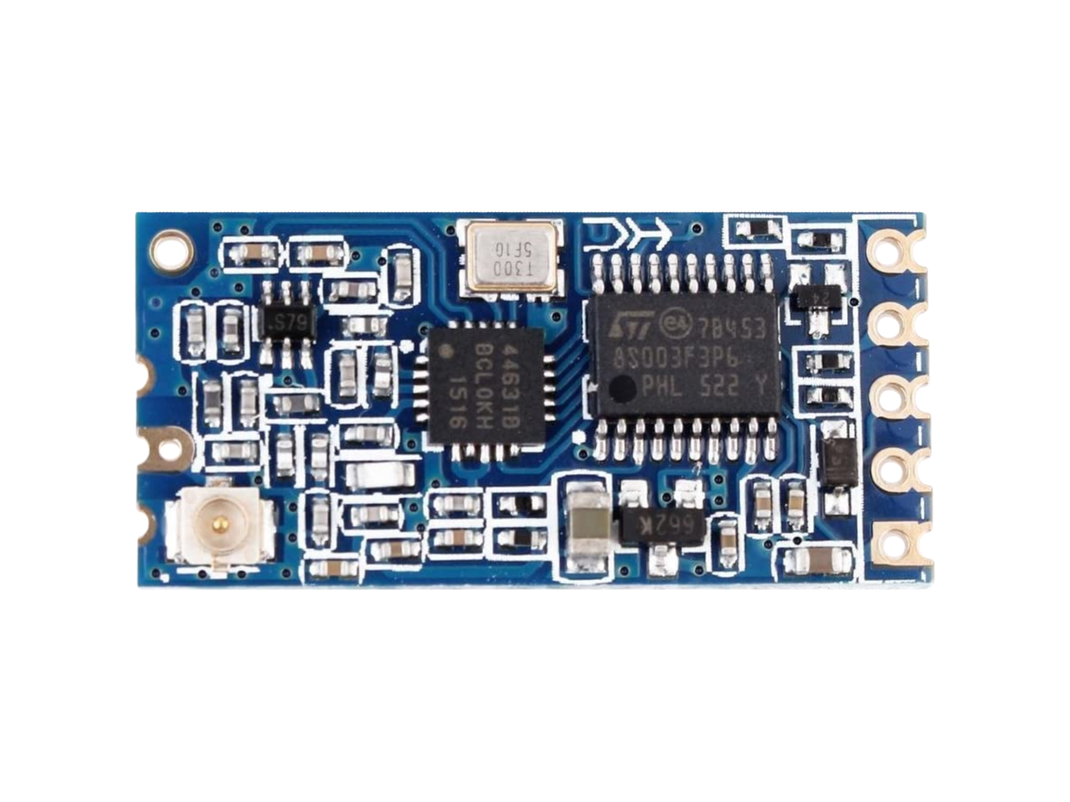
The HC-12 Wireless Serial Module, manufactured by Evelta, is a versatile wireless communication module designed for serial data transmission. Operating in the 433 MHz frequency range, it supports communication over distances of up to 1,000 meters in open space. The module is highly configurable, offering multiple communication modes to suit various applications. Its compact size and ease of use make it a popular choice for remote control, telemetry, and wireless data transfer projects.

Explore Projects Built with HC-12 Wireless Serial Module

Use Cirkit Designer to design, explore, and prototype these projects online. Some projects support real-time simulation. Click "Open Project" to start designing instantly!
STM32F103C8T6-Based Water Level Monitoring and Communication System with SIM900A and LoRa Connectivity
Image of water level: A project utilizing HC-12 Wireless Serial Module in a practical application
This circuit features a microcontroller (STM32F103C8T6) interfaced with a SIM900A GSM module, an HC-SR04 ultrasonic sensor, a water level sensor, and a LoRa Ra-02 SX1278 module for long-range communication. The STM32F103C8T6 is configured to communicate with the GSM module and LoRa module via serial connections, and it reads data from the ultrasonic and water level sensors. An FTDI Programmer is connected for programming and serial communication with the microcontroller.
Cirkit Designer LogoOpen Project in Cirkit Designer
Battery-Powered nRF52840 and HT-RA62 Communication Module
Image of NRF52840+HT-RA62: A project utilizing HC-12 Wireless Serial Module in a practical application
This circuit is a wireless communication system powered by a 18650 Li-ion battery, featuring an nRF52840 ProMicro microcontroller and an HT-RA62 transceiver module. The nRF52840 handles the control logic and interfaces with the HT-RA62 for data transmission, while the battery provides the necessary power for the entire setup.
Cirkit Designer LogoOpen Project in Cirkit Designer
Cellular-Enabled IoT Device with Real-Time Clock and Power Management
Image of LRCM PHASE 2 BASIC: A project utilizing HC-12 Wireless Serial Module in a practical application
This circuit features a LilyGo-SIM7000G module for cellular communication and GPS functionality, interfaced with an RTC DS3231 for real-time clock capabilities. It includes voltage sensing through two voltage sensor modules, and uses an 8-channel opto-coupler for isolating different parts of the circuit. Power management is handled by a buck converter connected to a DC power source and batteries, with a fuse for protection and a rocker switch for on/off control. Additionally, there's an LED for indication purposes.
Cirkit Designer LogoOpen Project in Cirkit Designer
Arduino Nano and LoRa SX1278 Battery-Powered Wireless Display
Image of transreciver: A project utilizing HC-12 Wireless Serial Module in a practical application
This circuit is a LoRa-based wireless communication system using an Arduino Nano to receive data packets and display them on an LCD. It includes a LoRa Ra-02 SX1278 module for long-range communication, a 3.7V battery with a charger module for power, and an LED indicator controlled by the Arduino.
Cirkit Designer LogoOpen Project in Cirkit Designer

Explore Projects Built with HC-12 Wireless Serial Module

Use Cirkit Designer to design, explore, and prototype these projects online. Some projects support real-time simulation. Click "Open Project" to start designing instantly!
Image of water level: A project utilizing HC-12 Wireless Serial Module in a practical application
STM32F103C8T6-Based Water Level Monitoring and Communication System with SIM900A and LoRa Connectivity
This circuit features a microcontroller (STM32F103C8T6) interfaced with a SIM900A GSM module, an HC-SR04 ultrasonic sensor, a water level sensor, and a LoRa Ra-02 SX1278 module for long-range communication. The STM32F103C8T6 is configured to communicate with the GSM module and LoRa module via serial connections, and it reads data from the ultrasonic and water level sensors. An FTDI Programmer is connected for programming and serial communication with the microcontroller.
Cirkit Designer LogoOpen Project in Cirkit Designer
Image of NRF52840+HT-RA62: A project utilizing HC-12 Wireless Serial Module in a practical application
Battery-Powered nRF52840 and HT-RA62 Communication Module
This circuit is a wireless communication system powered by a 18650 Li-ion battery, featuring an nRF52840 ProMicro microcontroller and an HT-RA62 transceiver module. The nRF52840 handles the control logic and interfaces with the HT-RA62 for data transmission, while the battery provides the necessary power for the entire setup.
Cirkit Designer LogoOpen Project in Cirkit Designer
Image of LRCM PHASE 2 BASIC: A project utilizing HC-12 Wireless Serial Module in a practical application
Cellular-Enabled IoT Device with Real-Time Clock and Power Management
This circuit features a LilyGo-SIM7000G module for cellular communication and GPS functionality, interfaced with an RTC DS3231 for real-time clock capabilities. It includes voltage sensing through two voltage sensor modules, and uses an 8-channel opto-coupler for isolating different parts of the circuit. Power management is handled by a buck converter connected to a DC power source and batteries, with a fuse for protection and a rocker switch for on/off control. Additionally, there's an LED for indication purposes.
Cirkit Designer LogoOpen Project in Cirkit Designer
Image of transreciver: A project utilizing HC-12 Wireless Serial Module in a practical application
Arduino Nano and LoRa SX1278 Battery-Powered Wireless Display
This circuit is a LoRa-based wireless communication system using an Arduino Nano to receive data packets and display them on an LCD. It includes a LoRa Ra-02 SX1278 module for long-range communication, a 3.7V battery with a charger module for power, and an LED indicator controlled by the Arduino.
Cirkit Designer LogoOpen Project in Cirkit Designer

Common Applications and Use Cases

  • Remote control systems (e.g., drones, robots)
  • Telemetry and sensor data transmission
  • Home automation and IoT devices
  • Wireless serial communication between microcontrollers
  • Industrial monitoring and control systems

Technical Specifications

The HC-12 module is designed to provide reliable and efficient wireless communication. Below are its key technical details:

Parameter Specification
Operating Frequency 433.4 MHz to 473.0 MHz
Communication Distance Up to 1,000 meters (open space)
Modulation Method GFSK (Gaussian Frequency Shift Keying)
Operating Voltage 3.2V to 5.5V
Operating Current 16 mA (transmitting), 3.5 mA (receiving)
Baud Rate 1,200 bps to 115,200 bps
Communication Modes FU1, FU2, FU3, FU4
Dimensions 27.8 mm x 14.4 mm x 4 mm
Operating Temperature -40°C to +85°C

Pin Configuration and Descriptions

The HC-12 module has a total of 4 pins. Below is the pinout and description:

Pin Name Description
1 VCC Power supply input (3.2V to 5.5V). Connect to the 5V or 3.3V pin of your microcontroller.
2 GND Ground. Connect to the ground of your circuit.
3 TXD Transmit data pin. Connect to the RX pin of your microcontroller.
4 RXD Receive data pin. Connect to the TX pin of your microcontroller.

Usage Instructions

The HC-12 module is straightforward to use and can be easily integrated into a circuit for wireless communication. Below are the steps and best practices for using the module:

Connecting the HC-12 to a Microcontroller

  1. Power Supply: Connect the VCC pin to a 3.3V or 5V power source and the GND pin to the ground.
  2. Serial Communication: Connect the TXD pin of the HC-12 to the RX pin of your microcontroller, and the RXD pin of the HC-12 to the TX pin of your microcontroller.
  3. Antenna: Attach an appropriate 433 MHz antenna to the module for optimal range and performance.

Configuring the HC-12

The HC-12 module can be configured using AT commands sent via a serial interface. To enter AT command mode:

  • Pull the "SET" pin (not listed in the basic pinout above) low before powering the module.
  • Use a serial terminal or microcontroller to send AT commands.

Example AT commands:

  • AT: Test the module's response.
  • AT+BAUDx: Set the baud rate (replace x with the desired value, e.g., AT+BAUD4 for 9600 bps).
  • AT+RFx: Set the communication channel (replace x with a value from 1 to 100).

Example: Using HC-12 with Arduino UNO

Below is an example of how to use the HC-12 module with an Arduino UNO for basic wireless communication:

#include <SoftwareSerial.h>

// Define RX and TX pins for HC-12
SoftwareSerial HC12(10, 11); // RX = Pin 10, TX = Pin 11

void setup() {
  Serial.begin(9600);       // Start serial communication with PC
  HC12.begin(9600);         // Start serial communication with HC-12
  Serial.println("HC-12 Ready");
}

void loop() {
  // Check if data is received from the HC-12 module
  if (HC12.available()) {
    String receivedData = HC12.readString();
    Serial.print("Received: ");
    Serial.println(receivedData); // Print received data to Serial Monitor
  }

  // Check if data is sent from the Serial Monitor
  if (Serial.available()) {
    String sendData = Serial.readString();
    HC12.print(sendData);   // Send data to HC-12 module
  }
}

Best Practices

  • Use a decoupling capacitor (e.g., 10 µF) across the VCC and GND pins to stabilize the power supply.
  • Ensure the antenna is securely connected for maximum range.
  • Avoid placing the module near high-frequency noise sources to prevent interference.

Troubleshooting and FAQs

Common Issues and Solutions

  1. No Communication Between Modules

    • Ensure both modules are configured to the same baud rate and communication mode.
    • Verify the TX and RX connections are correct.
  2. Short Communication Range

    • Check the antenna connection and ensure it is suitable for 433 MHz.
    • Avoid obstructions and interference sources in the communication path.
  3. Module Not Responding to AT Commands

    • Ensure the "SET" pin is pulled low before powering the module.
    • Verify the baud rate of the serial terminal matches the module's default baud rate (9600 bps).
  4. Data Loss or Corruption

    • Use a lower baud rate for long-distance communication to improve reliability.
    • Ensure a stable power supply to the module.

FAQs

Q: Can the HC-12 module communicate with other 433 MHz devices?
A: The HC-12 is designed to communicate with other HC-12 modules. It may not be compatible with other 433 MHz devices unless they use the same protocol and settings.

Q: How do I reset the HC-12 to factory settings?
A: Send the AT+DEFAULT command in AT mode to reset the module to its default configuration.

Q: What is the default baud rate of the HC-12?
A: The default baud rate is 9600 bps.

Q: Can I use the HC-12 with a 3.3V microcontroller?
A: Yes, the HC-12 supports an operating voltage range of 3.2V to 5.5V, making it compatible with both 3.3V and 5V systems.