Cirkit Designer Logo
Cirkit Designer
Your all-in-one circuit design IDE
Home / 
Component Documentation

How to Use SEN0427: Examples, Pinouts, and Specs
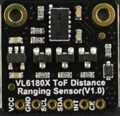
Image of SEN0427
Cirkit Designer LogoDesign with SEN0427 in Cirkit Designer

Introduction

The SEN0427 is a high-precision digital temperature and humidity sensor module designed by DFRobot. It utilizes the I2C communication protocol to provide accurate environmental readings, making it suitable for a wide range of applications including weather stations, home automation systems, and environmental monitoring.

Explore Projects Built with SEN0427

Use Cirkit Designer to design, explore, and prototype these projects online. Some projects support real-time simulation. Click "Open Project" to start designing instantly!
Battery-Powered Emergency Alert System with NUCLEO-F072RB, SIM800L, and GPS NEO 6M
Image of women safety: A project utilizing SEN0427 in a practical application
This circuit is an emergency alert system that uses a NUCLEO-F072RB microcontroller to send SMS alerts and make calls via a SIM800L GSM module, while obtaining location data from a GPS NEO 6M module. The system is powered by a Li-ion battery and includes a TP4056 module for battery charging and protection, with a rocker switch to control power to the microcontroller.
Cirkit Designer LogoOpen Project in Cirkit Designer
Cellular-Enabled IoT Device with Real-Time Clock and Power Management
Image of LRCM PHASE 2 BASIC: A project utilizing SEN0427 in a practical application
This circuit features a LilyGo-SIM7000G module for cellular communication and GPS functionality, interfaced with an RTC DS3231 for real-time clock capabilities. It includes voltage sensing through two voltage sensor modules, and uses an 8-channel opto-coupler for isolating different parts of the circuit. Power management is handled by a buck converter connected to a DC power source and batteries, with a fuse for protection and a rocker switch for on/off control. Additionally, there's an LED for indication purposes.
Cirkit Designer LogoOpen Project in Cirkit Designer
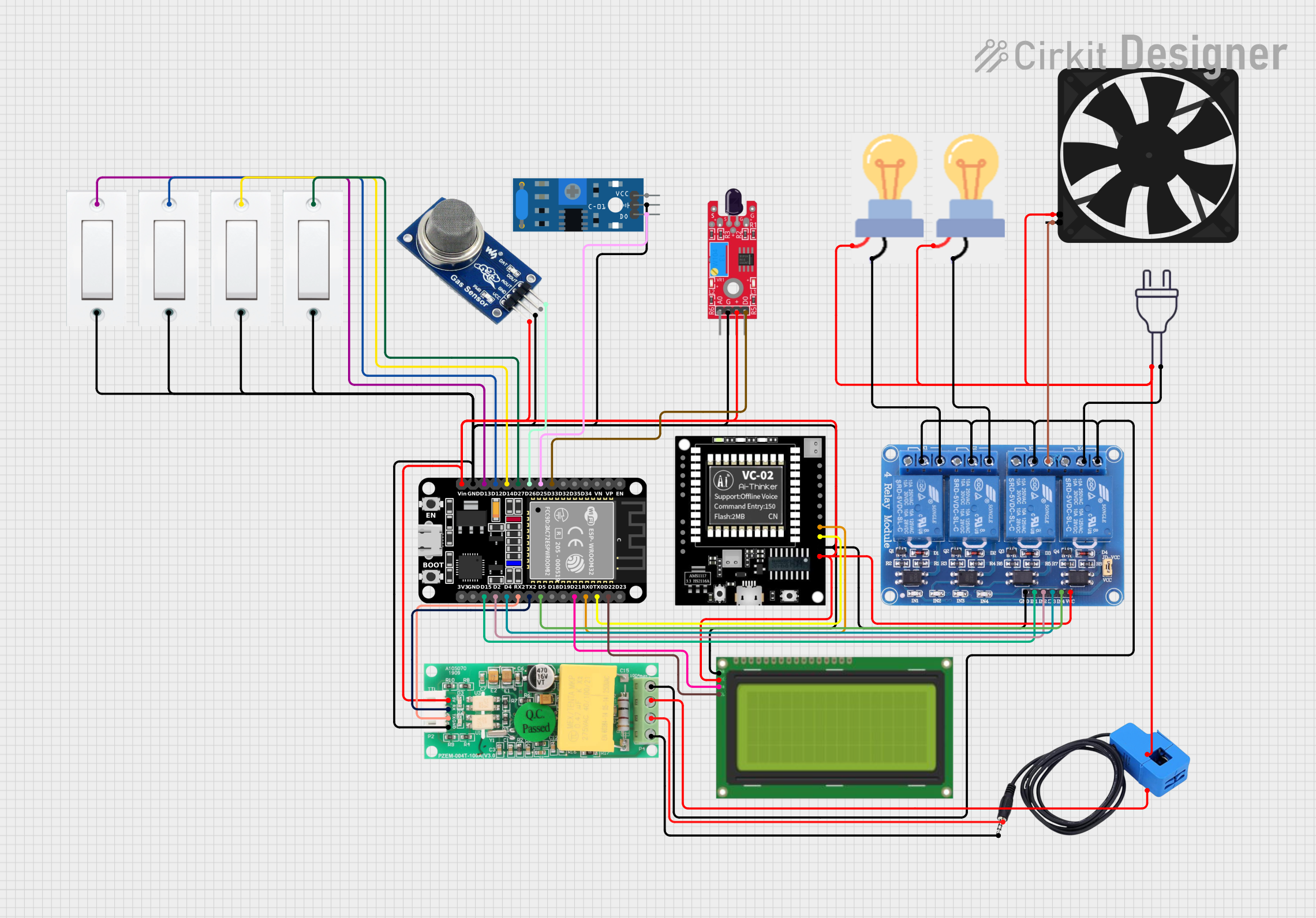
ESP32-Based Smart Environmental Monitoring System with Relay Control
Image of SOCOTECO: A project utilizing SEN0427 in a practical application
This is a smart environmental monitoring and control system featuring an ESP32 microcontroller interfaced with a PZEM004T for power monitoring, relay modules for actuating bulbs and a fan, and an LCD for user interface. It includes flame, gas, and vibration sensors for safety monitoring purposes.
Cirkit Designer LogoOpen Project in Cirkit Designer
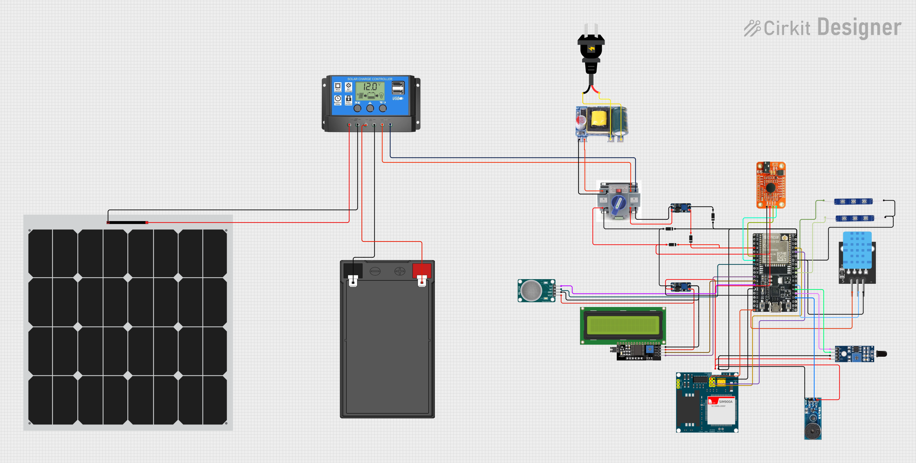
Solar-Powered Environmental Monitoring Station with GSM Reporting
Image of thesis nila po: A project utilizing SEN0427 in a practical application
This is a solar-powered monitoring and control system with automatic power source selection, environmental sensing, and communication capabilities. It uses an ESP32 microcontroller to process inputs from gas, flame, and temperature sensors, and to manage outputs like an LCD display, LEDs, and a buzzer. The system can communicate via a SIM900A module and switch between solar and AC power sources using an ATS.
Cirkit Designer LogoOpen Project in Cirkit Designer

Explore Projects Built with SEN0427

Use Cirkit Designer to design, explore, and prototype these projects online. Some projects support real-time simulation. Click "Open Project" to start designing instantly!
Image of women safety: A project utilizing SEN0427 in a practical application
Battery-Powered Emergency Alert System with NUCLEO-F072RB, SIM800L, and GPS NEO 6M
This circuit is an emergency alert system that uses a NUCLEO-F072RB microcontroller to send SMS alerts and make calls via a SIM800L GSM module, while obtaining location data from a GPS NEO 6M module. The system is powered by a Li-ion battery and includes a TP4056 module for battery charging and protection, with a rocker switch to control power to the microcontroller.
Cirkit Designer LogoOpen Project in Cirkit Designer
Image of LRCM PHASE 2 BASIC: A project utilizing SEN0427 in a practical application
Cellular-Enabled IoT Device with Real-Time Clock and Power Management
This circuit features a LilyGo-SIM7000G module for cellular communication and GPS functionality, interfaced with an RTC DS3231 for real-time clock capabilities. It includes voltage sensing through two voltage sensor modules, and uses an 8-channel opto-coupler for isolating different parts of the circuit. Power management is handled by a buck converter connected to a DC power source and batteries, with a fuse for protection and a rocker switch for on/off control. Additionally, there's an LED for indication purposes.
Cirkit Designer LogoOpen Project in Cirkit Designer
Image of SOCOTECO: A project utilizing SEN0427 in a practical application
ESP32-Based Smart Environmental Monitoring System with Relay Control
This is a smart environmental monitoring and control system featuring an ESP32 microcontroller interfaced with a PZEM004T for power monitoring, relay modules for actuating bulbs and a fan, and an LCD for user interface. It includes flame, gas, and vibration sensors for safety monitoring purposes.
Cirkit Designer LogoOpen Project in Cirkit Designer
Image of thesis nila po: A project utilizing SEN0427 in a practical application
Solar-Powered Environmental Monitoring Station with GSM Reporting
This is a solar-powered monitoring and control system with automatic power source selection, environmental sensing, and communication capabilities. It uses an ESP32 microcontroller to process inputs from gas, flame, and temperature sensors, and to manage outputs like an LCD display, LEDs, and a buzzer. The system can communicate via a SIM900A module and switch between solar and AC power sources using an ATS.
Cirkit Designer LogoOpen Project in Cirkit Designer

Technical Specifications

Key Technical Details

  • Operating Voltage: 3.3V to 5V
  • Measuring Range (Temperature): -40°C to 80°C
  • Measuring Range (Humidity): 0% to 100% RH
  • Accuracy (Temperature): ±0.5°C
  • Accuracy (Humidity): ±3% RH
  • Resolution (Temperature): 0.1°C
  • Resolution (Humidity): 0.1% RH
  • Communication: I2C interface

Pin Configuration and Descriptions

Pin Number Pin Name Description
1 VCC Power supply (3.3V to 5V)
2 GND Ground
3 SDA I2C Data Line
4 SCL I2C Clock Line

Usage Instructions

Integration with a Circuit

  1. Connect the VCC pin to the power supply (3.3V or 5V) of your microcontroller.
  2. Connect the GND pin to the ground of your microcontroller.
  3. Connect the SDA pin to the I2C data line on your microcontroller.
  4. Connect the SCL pin to the I2C clock line on your microcontroller.

I2C Communication

  • Ensure that the I2C address of the SEN0427 is not conflicting with other I2C devices on the same bus.
  • Use pull-up resistors on the SDA and SCL lines if your microcontroller does not have built-in pull-ups.

Best Practices

  • Avoid placing the sensor in direct sunlight or near heat sources to prevent inaccurate readings.
  • Ensure that the sensor is not exposed to condensing levels of humidity.
  • Allow the sensor to acclimatize to the environment for accurate readings.

Example Code for Arduino UNO

#include <Wire.h>

// SEN0427 I2C address (check datasheet for your specific device)
const int sensorAddress = 0xXX; // Replace 0xXX with the actual address

void setup() {
  Wire.begin(); // Initialize I2C communication
  Serial.begin(9600); // Start serial communication at 9600 baud rate
}

void loop() {
  // Request temperature and humidity data from SEN0427
  Wire.beginTransmission(sensorAddress);
  // Add code to request data following the sensor's datasheet instructions
  Wire.endTransmission();
  
  // Read the data from the sensor
  // Add code to read and process the data according to the sensor's datasheet
  
  // Example of printing the temperature and humidity values
  Serial.print("Temperature: ");
  Serial.print(temperature);
  Serial.println(" C");
  
  Serial.print("Humidity: ");
  Serial.print(humidity);
  Serial.println(" %");
  
  // Delay between measurements
  delay(2000);
}

Note: Replace 0xXX with the actual I2C address of your SEN0427 sensor. The code above is a template and requires the specific data request and read commands as per the SEN0427 datasheet.

Troubleshooting and FAQs

Common Issues

  • Inaccurate Readings: Ensure the sensor is not placed near heat sources or in direct sunlight. Allow it to acclimatize.
  • No Data on I2C: Check connections and ensure that the correct I2C address is used. Also, check for proper pull-up resistors.

Solutions and Tips

  • Sensor Not Detected: Verify wiring, check for soldering issues, and ensure that the microcontroller's I2C lines are functioning.
  • Fluctuating Readings: Implement a software filter or moving average to stabilize readings.

FAQs

Q: Can the SEN0427 sensor be used outdoors? A: Yes, but it should be protected from direct sunlight and water.

Q: What is the I2C address of the SEN0427 sensor? A: The I2C address can vary; refer to the datasheet or use an I2C scanner sketch to determine the address.

Q: How long does the sensor need to acclimatize? A: It typically takes a few minutes for the sensor to stabilize after being exposed to a new environment.

Q: Can I use multiple SEN0427 sensors on the same I2C bus? A: Yes, as long as each sensor has a unique I2C address.

For further assistance, please refer to the DFRobot SEN0427 datasheet or contact technical support.