Cirkit Designer Logo
Cirkit Designer
Your all-in-one circuit design IDE
Home / 
Component Documentation

How to Use HT-12D: Examples, Pinouts, and Specs

Image of HT-12D
Cirkit Designer LogoDesign with HT-12D in Cirkit Designer

Introduction

The HT-12D is a 12-bit addressable decoder IC manufactured by Holtek, with the part ID B544G1106G2. It is widely used in remote control applications to decode serial data transmitted by an encoder, such as the HT-12E. The IC is designed to work in RF communication systems, enabling wireless data transmission for devices like garage door openers, home automation systems, and security systems.

The HT-12D decodes 12-bit data, which consists of 8 address bits and 4 data bits. It ensures secure communication by matching the address bits of the transmitter and receiver. This makes it ideal for applications requiring reliable and interference-free wireless communication.

Explore Projects Built with HT-12D

Use Cirkit Designer to design, explore, and prototype these projects online. Some projects support real-time simulation. Click "Open Project" to start designing instantly!
STM32H7-Based Multi-Sensor Monitoring System with GSM Alert and LCD Display
Image of medical: A project utilizing HT-12D in a practical application
This circuit is centered around an STM32H7 microcontroller, which interfaces with a variety of sensors including a DHT11 temperature and humidity sensor, a DS3231 real-time clock, an MQ-2 smoke detector, an IR sensor, a MAX30102 pulse oximeter, and a body temperature sensor. It also includes a GSM module for communication, an LCD display for output, multiple pushbuttons for input, a buzzer, and a speaker for audio signaling. The microcontroller's embedded code suggests that it is programmed to periodically read from the sensors, handle button inputs, update the LCD display, and potentially send alerts via the GSM module.
Cirkit Designer LogoOpen Project in Cirkit Designer
Wi-Fi Controlled Weather Station with Wemos D1 Mini and OLED Display
Image of izdelie_3: A project utilizing HT-12D in a practical application
This circuit is a weather monitoring system that uses a Wemos D1 Mini microcontroller to read temperature and humidity data from four DHT22 sensors and display the information on an Adafruit OLED screen. The data is also transmitted via WiFi to an MQTT server for remote monitoring. The system is powered by a 2000mAh battery, which is managed by a TP4056 charging module and a Mtiny Power module.
Cirkit Designer LogoOpen Project in Cirkit Designer
ESP8266 NodeMCU-Based Environmental Monitoring System with SIM900A GSM Communication
Image of IOE: A project utilizing HT-12D in a practical application
This is a sensor-based data acquisition system with GSM communication capability. It uses an ESP8266 NodeMCU to collect environmental data from a DHT22 sensor and light levels from an LDR, as well as distance measurements from an HC-SR04 ultrasonic sensor. The SIM900A GSM module enables the system to transmit the collected data over a cellular network.
Cirkit Designer LogoOpen Project in Cirkit Designer
Arduino and ESP8266 Based Smart Climate Control and Lighting System
Image of Smart Home: A project utilizing HT-12D in a practical application
This circuit is designed for environmental monitoring and control, featuring an Arduino UNO microcontroller that interfaces with a DHT11 temperature and humidity sensor, an LDR for light level detection, a PIR motion sensor, and a real-time clock (RTC DS3231). It uses a 12V battery charged by a solar panel through an MPPT SCC, with a step-down converter to provide 5V power. The Arduino controls relays to manage an AC LED bulb and a fan, with manual override available via Bluetooth communication.
Cirkit Designer LogoOpen Project in Cirkit Designer

Explore Projects Built with HT-12D

Use Cirkit Designer to design, explore, and prototype these projects online. Some projects support real-time simulation. Click "Open Project" to start designing instantly!
Image of medical: A project utilizing HT-12D in a practical application
STM32H7-Based Multi-Sensor Monitoring System with GSM Alert and LCD Display
This circuit is centered around an STM32H7 microcontroller, which interfaces with a variety of sensors including a DHT11 temperature and humidity sensor, a DS3231 real-time clock, an MQ-2 smoke detector, an IR sensor, a MAX30102 pulse oximeter, and a body temperature sensor. It also includes a GSM module for communication, an LCD display for output, multiple pushbuttons for input, a buzzer, and a speaker for audio signaling. The microcontroller's embedded code suggests that it is programmed to periodically read from the sensors, handle button inputs, update the LCD display, and potentially send alerts via the GSM module.
Cirkit Designer LogoOpen Project in Cirkit Designer
Image of izdelie_3: A project utilizing HT-12D in a practical application
Wi-Fi Controlled Weather Station with Wemos D1 Mini and OLED Display
This circuit is a weather monitoring system that uses a Wemos D1 Mini microcontroller to read temperature and humidity data from four DHT22 sensors and display the information on an Adafruit OLED screen. The data is also transmitted via WiFi to an MQTT server for remote monitoring. The system is powered by a 2000mAh battery, which is managed by a TP4056 charging module and a Mtiny Power module.
Cirkit Designer LogoOpen Project in Cirkit Designer
Image of IOE: A project utilizing HT-12D in a practical application
ESP8266 NodeMCU-Based Environmental Monitoring System with SIM900A GSM Communication
This is a sensor-based data acquisition system with GSM communication capability. It uses an ESP8266 NodeMCU to collect environmental data from a DHT22 sensor and light levels from an LDR, as well as distance measurements from an HC-SR04 ultrasonic sensor. The SIM900A GSM module enables the system to transmit the collected data over a cellular network.
Cirkit Designer LogoOpen Project in Cirkit Designer
Image of Smart Home: A project utilizing HT-12D in a practical application
Arduino and ESP8266 Based Smart Climate Control and Lighting System
This circuit is designed for environmental monitoring and control, featuring an Arduino UNO microcontroller that interfaces with a DHT11 temperature and humidity sensor, an LDR for light level detection, a PIR motion sensor, and a real-time clock (RTC DS3231). It uses a 12V battery charged by a solar panel through an MPPT SCC, with a step-down converter to provide 5V power. The Arduino controls relays to manage an AC LED bulb and a fan, with manual override available via Bluetooth communication.
Cirkit Designer LogoOpen Project in Cirkit Designer

Technical Specifications

  • Manufacturer: Holtek
  • Part ID: B544G1106G2
  • Operating Voltage: 2.4V to 12V DC
  • Operating Current: 0.4 mA (typical at 5V)
  • Decoding Capability: 12-bit (8 address bits + 4 data bits)
  • Output Type: CMOS
  • Operating Frequency: Compatible with RF modules (e.g., 433 MHz)
  • Operating Temperature: -20°C to +75°C
  • Package Type: DIP-18 or SOP-18

Pin Configuration and Descriptions

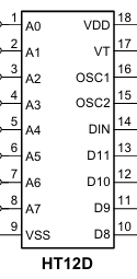
The HT-12D has 18 pins, as described in the table below:

Pin Number Pin Name Description
1-8 A0-A7 Address input pins. Used to set the 8-bit address for communication.
9 Ground (VSS) Ground pin. Connect to the negative terminal of the power supply.
10 DIN Data input pin. Connect to the data output of the RF receiver module.
11-14 D0-D3 Data output pins. Outputs the decoded 4-bit data.
15 VT Valid transmission pin. Goes HIGH when valid data is received.
16 Oscillator 1 Connect to an external resistor to set the oscillator frequency.
17 Oscillator 2 Connect to an external resistor to set the oscillator frequency.
18 VDD Positive power supply pin. Connect to the positive terminal of the power supply.

Usage Instructions

How to Use the HT-12D in a Circuit

  1. Power Supply: Connect the VDD pin to a DC voltage source (2.4V to 12V) and the VSS pin to ground.
  2. Address Configuration: Set the address pins (A0-A7) to match the address of the transmitter (e.g., HT-12E). Use pull-up or pull-down resistors to set each pin HIGH or LOW.
  3. Oscillator Setup: Connect a resistor (typically 1MΩ) between the Oscillator 1 and Oscillator 2 pins to set the internal clock frequency.
  4. Data Input: Connect the DIN pin to the data output of an RF receiver module.
  5. Data Output: The decoded 4-bit data will be available on the D0-D3 pins. The VT pin will go HIGH when valid data is received.

Important Considerations and Best Practices

  • Ensure that the address pins of the HT-12D match the address pins of the transmitter (e.g., HT-12E) for proper communication.
  • Use decoupling capacitors (e.g., 0.1 µF) near the VDD pin to reduce noise and stabilize the power supply.
  • The resistor value connected to the oscillator pins determines the operating frequency. Refer to the datasheet for recommended values.
  • Use proper RF modules (e.g., 433 MHz) for reliable wireless communication.

Example: Connecting HT-12D to an Arduino UNO

The HT-12D can be interfaced with an Arduino UNO to read the decoded data. Below is an example code snippet:

// Define the data output pins of the HT-12D
#define D0 2  // Connect HT-12D D0 pin to Arduino digital pin 2
#define D1 3  // Connect HT-12D D1 pin to Arduino digital pin 3
#define D2 4  // Connect HT-12D D2 pin to Arduino digital pin 4
#define D3 5  // Connect HT-12D D3 pin to Arduino digital pin 5
#define VT 6  // Connect HT-12D VT pin to Arduino digital pin 6

void setup() {
  // Set the data pins as input
  pinMode(D0, INPUT);
  pinMode(D1, INPUT);
  pinMode(D2, INPUT);
  pinMode(D3, INPUT);
  pinMode(VT, INPUT);

  // Initialize serial communication for debugging
  Serial.begin(9600);
}

void loop() {
  // Check if valid data is received
  if (digitalRead(VT) == HIGH) {
    // Read the 4-bit data from the HT-12D
    int data = (digitalRead(D3) << 3) | (digitalRead(D2) << 2) |
               (digitalRead(D1) << 1) | digitalRead(D0);

    // Print the received data to the Serial Monitor
    Serial.print("Received Data: ");
    Serial.println(data, BIN);  // Print data in binary format
  }
}

Troubleshooting and FAQs

Common Issues and Solutions

  1. No Output on Data Pins:

    • Ensure the address pins of the HT-12D match the address pins of the transmitter.
    • Verify that the RF receiver module is functioning correctly and is properly connected to the DIN pin.
  2. VT Pin Not Going HIGH:

    • Check the power supply voltage and ensure it is within the operating range (2.4V to 12V).
    • Verify the resistor value connected to the oscillator pins. Incorrect values can cause decoding issues.
  3. Interference in Wireless Communication:

    • Use RF modules with proper shielding and ensure there is minimal interference in the operating frequency range.
    • Match the operating frequency of the transmitter and receiver modules (e.g., 433 MHz).

FAQs

Q1: Can the HT-12D be used with any RF module?
A1: The HT-12D is compatible with most RF modules operating at standard frequencies like 433 MHz. Ensure the module supports serial data transmission.

Q2: What is the maximum range of communication?
A2: The range depends on the RF module used. Typically, 433 MHz modules can achieve a range of 50-100 meters in open space.

Q3: Can I use fewer address pins?
A3: Yes, unused address pins can be left floating or tied to ground. However, ensure the same configuration is used on the transmitter side.

Q4: What happens if the address pins do not match?
A4: The HT-12D will not decode the data, and the VT pin will remain LOW.