How to Use Passive Buzzer Module: Examples, Pinouts, and Specs

 Design with Passive Buzzer Module in Cirkit Designer
Introduction
The Passive Buzzer Module by Robocraze, part ID RC-B-552, is an electronic sound-generating device that requires an external signal to produce tones. Unlike active buzzers that have an internal oscillator, passive buzzers need to be driven by an external pulse-width modulated (PWM) signal to generate various tones and sounds. This makes them highly versatile for creating different sound effects and musical notes in applications such as alarms, notification systems, and DIY musical instruments.
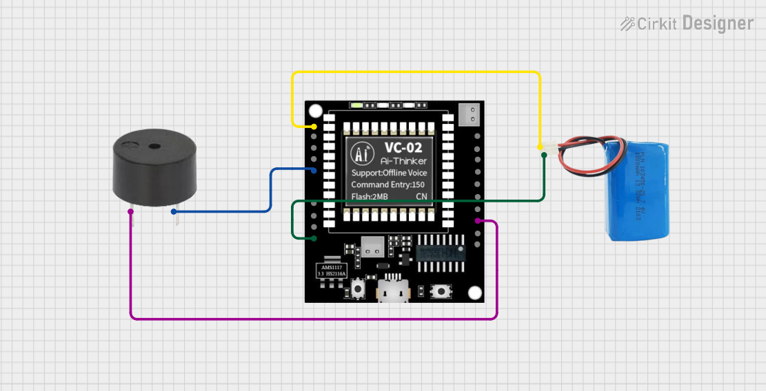
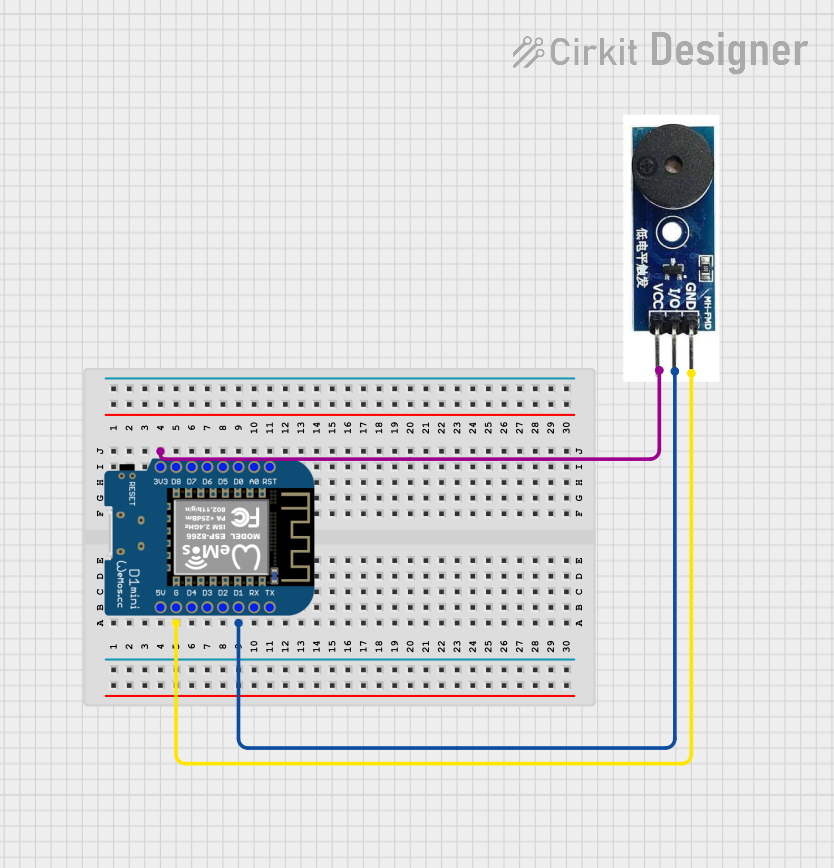
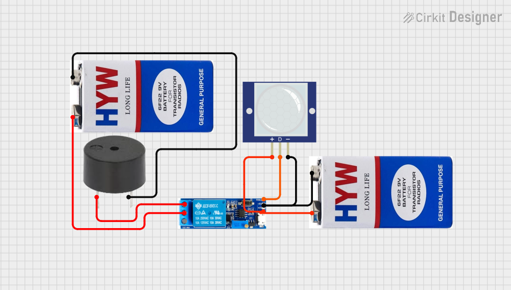
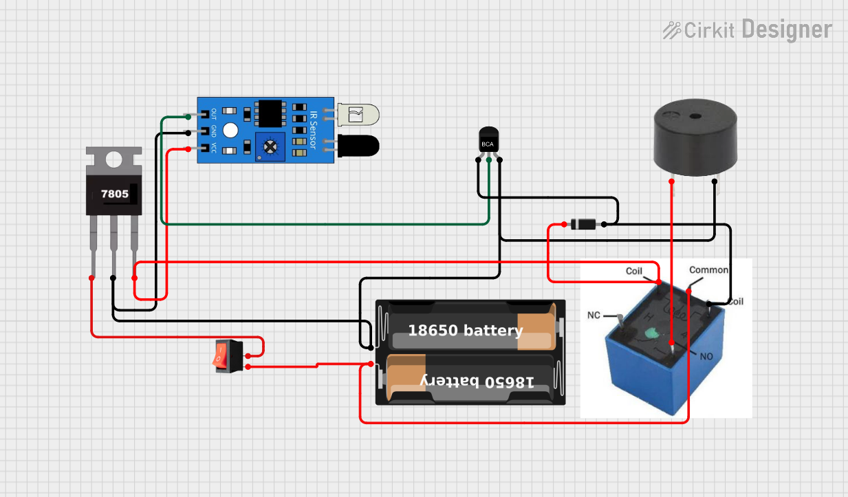
Explore Projects Built with Passive Buzzer Module

 Open Project in Cirkit Designer
 Open Project in Cirkit Designer
 Open Project in Cirkit Designer
 Open Project in Cirkit Designer
Explore Projects Built with Passive Buzzer Module

 Open Project in Cirkit Designer
 Open Project in Cirkit Designer
 Open Project in Cirkit Designer
 Open Project in Cirkit Designer
Technical Specifications
Key Technical Details
- Operating Voltage: 3.3V to 5V
- Rated Current: <30mA
- Sound Output Frequency: Dependent on input signal
- Sound Pressure Level: >85dB at 10cm
- Resonant Frequency: 2.5kHz ± 300Hz
Pin Configuration and Descriptions
| Pin Number | Pin Name | Description |
|---|---|---|
| 1 | VCC | Connect to 3.3V or 5V power supply |
| 2 | GND | Connect to the ground of the circuit |
| 3 | SIG | Signal input, connect to PWM output |
Usage Instructions
Connecting to a Circuit
- Connect the VCC pin to a 3.3V or 5V power supply.
- Connect the GND pin to the ground of your power supply.
- Connect the SIG pin to a PWM-capable pin on your microcontroller, such as an Arduino UNO.
Generating Sound
To generate sound with the passive buzzer module, you need to provide a PWM signal to the SIG pin. The frequency of the PWM signal will determine the pitch of the sound produced by the buzzer.
Example Code for Arduino UNO
// Define the buzzer pin
int buzzerPin = 9;

void setup() {
  // Set the buzzer pin as an output
  pinMode(buzzerPin, OUTPUT);
}

void loop() {
  // Generate a 1kHz tone for 1 second
  tone(buzzerPin, 1000, 1000);
  delay(1500); // Wait for 1.5 seconds

  // Generate a 500Hz tone for 1 second
  tone(buzzerPin, 500, 1000);
  delay(1500); // Wait for 1.5 seconds
}
Important Considerations and Best Practices
- Do not exceed the maximum rated voltage of 5V.
- Ensure the PWM signal frequency is within the audible range (20Hz to 20kHz) for human hearing.
- Use the
tone()function in Arduino to easily generate different frequencies. - Avoid continuous operation at high volume levels to prevent damage to the buzzer element.
Troubleshooting and FAQs
Common Issues
- No Sound: Ensure the buzzer is properly powered and the signal pin is connected to a PWM output.
- Low Volume: Check if the operating voltage is sufficient and within the specified range.
- Distorted Sound: Verify that the PWM signal frequency is within the buzzer's operating range.
Solutions and Tips
- Double-check wiring connections for any loose contacts or incorrect connections.
- Use a multimeter to verify the voltage at the VCC pin.
- If using an Arduino, ensure the
tone()function is correctly implemented in your code.
FAQs
Q: Can I use the passive buzzer module with a digital pin that is not PWM capable?
A: No, the passive buzzer requires a PWM signal to generate sound. A digital pin without PWM capability cannot provide the necessary signal.
Q: What is the difference between a passive and an active buzzer?
A: A passive buzzer requires an external PWM signal to produce sound, while an active buzzer has an internal oscillator and generates sound when powered.
Q: How can I play a melody with the passive buzzer?
A: You can play a melody by generating a sequence of PWM signals at different frequencies corresponding to the musical notes of the melody.
For further assistance or inquiries about the Passive Buzzer Module RC-B-552, please contact Robocraze customer support.