How to Use 3.12" OLED Display 256x64: Examples, Pinouts, and Specs
Introduction
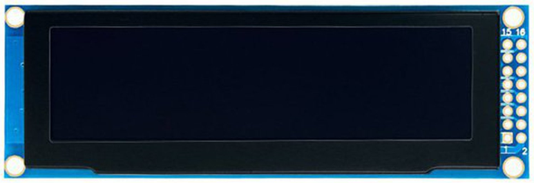
The 3.12" OLED Display 256x64 by ACEIRMC (Part ID: SSD1322) is a compact, high-resolution organic light-emitting diode (OLED) display module. With a resolution of 256x64 pixels, this display is ideal for applications requiring crisp graphics and text rendering. Its OLED technology ensures high contrast, wide viewing angles, and low power consumption, making it suitable for portable devices, industrial equipment, and consumer electronics.
Explore Projects Built with 3.12" OLED Display 256x64


Explore Projects Built with 3.12" OLED Display 256x64
Common Applications
- Wearable devices and smart gadgets
- Industrial control panels
- Consumer electronics (e.g., audio systems, gaming devices)
- IoT devices and embedded systems
- Medical equipment displays
Technical Specifications
Key Technical Details
| Parameter | Value |
|---|---|
| Manufacturer | ACEIRMC |
| Part ID | SSD1322 |
| Display Type | OLED (Organic Light-Emitting Diode) |
| Resolution | 256x64 pixels |
| Active Area | 69.14mm x 17.26mm |
| Interface | SPI (4-wire) / Parallel |
| Operating Voltage | 3.3V (logic) |
| Supply Voltage | 2.4V - 3.5V |
| Operating Temperature | -40°C to +85°C |
| Viewing Angle | >160° |
| Pixel Color | Monochrome (white or yellow) |
Pin Configuration and Descriptions
The SSD1322 OLED display module typically has a 24-pin interface. Below is the pinout description:
| Pin No. | Name | Type | Description |
|---|---|---|---|
| 1 | VCC | Power | Power supply (2.4V - 3.5V). |
| 2 | GND | Ground | Ground connection. |
| 3 | D0 | Input | Serial clock (SCLK) for SPI or data bus line 0. |
| 4 | D1 | Input | Serial data (MOSI) for SPI or data bus line 1. |
| 5 | RES | Input | Reset signal (active low). |
| 6 | DC | Input | Data/Command control pin. |
| 7 | CS | Input | Chip select (active low). |
| 8-23 | NC | - | Not connected (reserved for parallel interface). |
| 24 | VCOMH | Power | Voltage for common electrode driving. |
Note: Ensure the correct interface (SPI or parallel) is selected based on your application.
Usage Instructions
How to Use the Component in a Circuit
- Power Supply: Connect the VCC pin to a 3.3V power source and GND to ground.
- Interface Selection: By default, the SSD1322 operates in SPI mode. Ensure your microcontroller supports SPI communication.
- Connections:
- Connect the
D0(SCLK) andD1(MOSI) pins to the corresponding SPI pins on your microcontroller. - Use the
CSpin to enable or disable the display module. - The
RESpin should be connected to a GPIO pin for resetting the display. - The
DCpin determines whether the data sent is a command or display data.
- Connect the
- Initialization: Use the appropriate initialization sequence for the SSD1322 controller. This typically involves sending a series of commands to configure the display.
Important Considerations and Best Practices
- Voltage Levels: Ensure the logic voltage levels of your microcontroller match the display's requirements (3.3V).
- Reset Signal: Always reset the display during power-up to ensure proper initialization.
- ESD Protection: Handle the display carefully to avoid electrostatic discharge damage.
- Contrast Settings: Adjust the contrast settings via software commands for optimal visibility.
Example Code for Arduino UNO
Below is an example of how to interface the SSD1322 OLED display with an Arduino UNO using the SPI interface. This example uses the popular U8g2 library.
#include <U8g2lib.h>

// Initialize the display with U8g2 library in SPI mode
// U8G2_SSD1322_NHD_256X64_F_4W_HW_SPI: Constructor for SSD1322 in 4-wire SPI mode
U8G2_SSD1322_NHD_256X64_F_4W_HW_SPI u8g2(U8G2_R0, /* cs=*/ 10, /* dc=*/ 9, /* reset=*/ 8);

void setup() {
  u8g2.begin(); // Initialize the display
  u8g2.setContrast(200); // Set contrast (0-255)
}

void loop() {
  u8g2.clearBuffer(); // Clear the display buffer
  u8g2.setFont(u8g2_font_ncenB08_tr); // Set font
  u8g2.drawStr(0, 20, "Hello, OLED!"); // Draw text at (x=0, y=20)
  u8g2.sendBuffer(); // Send buffer to display
  delay(1000); // Wait for 1 second
}
Note: Install the
U8g2library in the Arduino IDE via the Library Manager before running the code.
Troubleshooting and FAQs
Common Issues and Solutions
Display Not Turning On:
- Verify the power supply voltage (2.4V - 3.5V).
- Check all connections, especially the
VCCandGNDpins. - Ensure the
CSpin is correctly configured and active.
No Output on Display:
- Confirm the SPI connections (
D0,D1,CS,DC,RES) are correct. - Ensure the initialization sequence is properly implemented in your code.
- Check for loose or faulty wiring.
- Confirm the SPI connections (
Flickering or Corrupted Display:
- Verify the SPI clock speed. Reduce it if necessary (e.g., below 8 MHz).
- Ensure proper grounding and minimize noise in the circuit.
Low Contrast or Dim Display:
- Adjust the contrast settings via software commands.
- Ensure the supply voltage is within the recommended range.
FAQs
Q1: Can I use this display with a 5V microcontroller?
A1: Yes, but you will need a level shifter to convert the 5V logic signals to 3.3V.
Q2: What is the maximum SPI clock speed supported?
A2: The SSD1322 supports SPI clock speeds up to 10 MHz. However, for stable operation, it is recommended to use speeds below 8 MHz.
Q3: Can I use this display in outdoor environments?
A3: Yes, the display operates in temperatures ranging from -40°C to +85°C, making it suitable for outdoor use.
Q4: Is the display compatible with other microcontrollers like ESP32 or STM32?
A4: Yes, the display can be used with any microcontroller that supports SPI or parallel communication.