How to Use Over Under Voltage: Examples, Pinouts, and Specs
Introduction
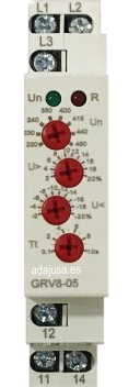
The Over Under Voltage device is a protective component designed to monitor voltage levels in an electrical circuit. It ensures the safety of connected equipment by disconnecting the load when the voltage exceeds or falls below preset thresholds. This prevents potential damage caused by overvoltage or undervoltage conditions.
Explore Projects Built with Over Under Voltage


Explore Projects Built with Over Under Voltage
Common Applications and Use Cases
- Protection of sensitive electronic devices in industrial and residential settings.
- Voltage regulation in power distribution systems.
- Safeguarding appliances such as refrigerators, air conditioners, and computers.
- Use in renewable energy systems to protect inverters and batteries.
Technical Specifications
The following table outlines the key technical details of the Over Under Voltage device:
| Parameter | Value |
|---|---|
| Operating Voltage Range | 100V AC to 300V AC |
| Overvoltage Threshold | Adjustable (e.g., 250V to 300V) |
| Undervoltage Threshold | Adjustable (e.g., 100V to 200V) |
| Response Time | < 1 second |
| Maximum Load Current | 10A |
| Power Consumption | < 2W |
| Operating Temperature | -10°C to 50°C |
| Dimensions | 90mm x 60mm x 40mm |
| Mounting Type | DIN Rail or Panel Mount |
Pin Configuration and Descriptions
The Over Under Voltage device typically has the following terminals:
| Pin/Terminal | Description |
|---|---|
| L (Line Input) | Connects to the live wire of the AC power source. |
| N (Neutral Input) | Connects to the neutral wire of the AC power source. |
| L (Load Output) | Connects to the live wire of the load. |
| N (Load Output) | Connects to the neutral wire of the load. |
Usage Instructions
How to Use the Component in a Circuit
Wiring the Device:
- Connect the live (L) and neutral (N) input terminals of the device to the AC power source.
- Connect the live (L) and neutral (N) output terminals to the load (e.g., an appliance or circuit to be protected).
- Ensure all connections are secure and insulated to prevent short circuits.
Adjusting Voltage Thresholds:
- Use the adjustment knobs or buttons (if available) to set the overvoltage and undervoltage thresholds according to the requirements of your load.
- Refer to the device's user manual for specific adjustment instructions.
Testing the Device:
- Power on the circuit and verify that the device operates within the set voltage range.
- Simulate overvoltage and undervoltage conditions to ensure the device disconnects the load as expected.
Important Considerations and Best Practices
- Always ensure the device's maximum load current rating is not exceeded.
- Install the device in a well-ventilated area to prevent overheating.
- Use appropriate fuses or circuit breakers for additional protection.
- Regularly inspect the device for signs of wear or damage.
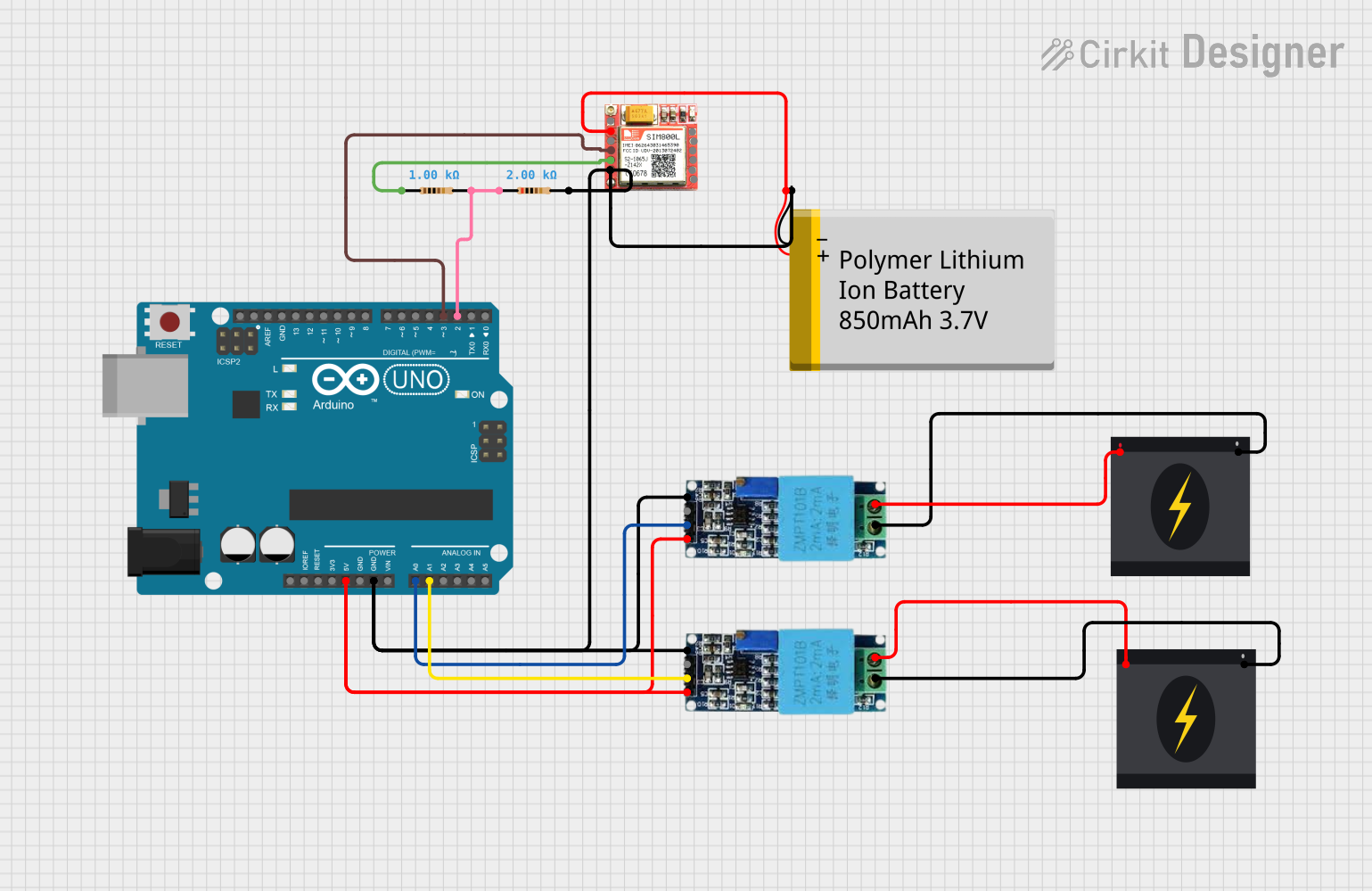
Example: Connecting to an Arduino UNO
While the Over Under Voltage device is not directly programmable, it can be used in conjunction with an Arduino UNO to monitor voltage levels. Below is an example of how to interface the device with an Arduino using a voltage sensor for additional monitoring:
// Example code to monitor voltage levels using an Arduino UNO
// and a voltage sensor. The Over Under Voltage device operates
// independently but can be monitored for additional safety.

const int voltagePin = A0; // Analog pin connected to the voltage sensor
float voltage = 0.0;       // Variable to store the measured voltage

void setup() {
  Serial.begin(9600); // Initialize serial communication
  pinMode(voltagePin, INPUT); // Set the voltage pin as input
}

void loop() {
  int sensorValue = analogRead(voltagePin); // Read the sensor value
  voltage = (sensorValue * 5.0) / 1023.0;   // Convert to voltage (assuming 5V ADC)
  voltage = voltage * 100; // Adjust based on sensor scaling (e.g., 100:1)

  // Print the voltage to the Serial Monitor
  Serial.print("Voltage: ");
  Serial.print(voltage);
  Serial.println(" V");

  // Add custom logic to trigger alerts or actions if needed
  if (voltage > 250.0) {
    Serial.println("Warning: Overvoltage detected!");
  } else if (voltage < 200.0) {
    Serial.println("Warning: Undervoltage detected!");
  }

  delay(1000); // Wait for 1 second before the next reading
}
Troubleshooting and FAQs
Common Issues and Solutions
Device Does Not Power On:
- Check the input wiring for loose or incorrect connections.
- Verify that the input voltage is within the operating range of the device.
Load Does Not Receive Power:
- Ensure the overvoltage and undervoltage thresholds are set correctly.
- Check for tripped circuit breakers or blown fuses in the circuit.
Frequent Tripping of the Device:
- Verify that the input voltage is stable and within the set thresholds.
- Inspect the load for faults or excessive current draw.
Device Overheats:
- Ensure proper ventilation around the device.
- Check that the load current does not exceed the device's maximum rating.
FAQs
Q: Can the device protect against short circuits?
A: No, the Over Under Voltage device is designed to protect against voltage fluctuations. Use a circuit breaker or fuse for short-circuit protection.
Q: How do I know if the device is working?
A: Most devices have indicator LEDs to show normal operation, overvoltage, or undervoltage conditions.
Q: Can I use this device with DC circuits?
A: No, this device is designed for AC circuits. For DC applications, use a DC-specific voltage protection device.
Q: What happens if the voltage returns to normal after a trip?
A: The device will automatically reconnect the load once the voltage stabilizes within the set thresholds.