
How to Use IEC320 C14 Power Inlet: Examples, Pinouts, and Specs
 Design with IEC320 C14 Power Inlet in Cirkit Designer
Introduction
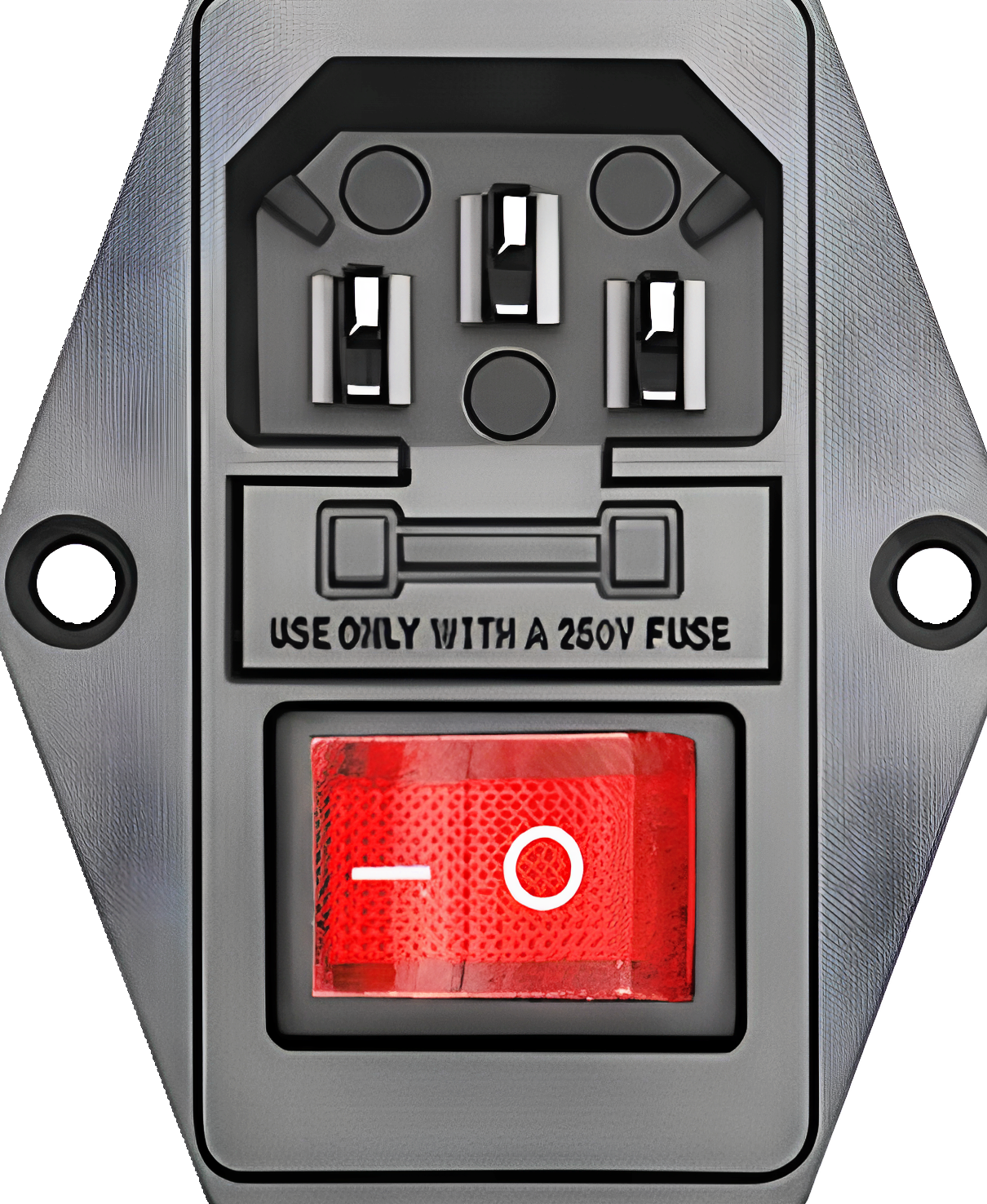
The IEC320 C14 Power Inlet is a standardized electrical connector commonly used for connecting power cords to electronic devices. It features a rectangular shape with three pins and a locking mechanism to ensure a secure and reliable connection. This component is widely used in power supplies, desktop computers, servers, and other electronic equipment requiring AC power input.
Explore Projects Built with IEC320 C14 Power Inlet
 Open Project in Cirkit Designer
 Open Project in Cirkit Designer
 Open Project in Cirkit Designer
 Open Project in Cirkit Designer
Explore Projects Built with IEC320 C14 Power Inlet
Open Project in Cirkit DesignerOpen Project in Cirkit DesignerOpen Project in Cirkit DesignerOpen Project in Cirkit DesignerCommon Applications and Use Cases
- Power input for desktop computers, servers, and monitors
- Power supplies for industrial and consumer electronics
- Test equipment and laboratory devices
- Audio and video equipment
- Uninterruptible Power Supplies (UPS)
Technical Specifications
Key Technical Details
| Parameter | Specification |
|---|---|
| Connector Type | IEC 60320 C14 |
| Rated Voltage | 250V AC |
| Rated Current | 10A (varies by model) |
| Number of Pins | 3 (Line, Neutral, Ground) |
| Mounting Style | Panel Mount |
| Operating Temperature | -25°C to +70°C |
| Material | Thermoplastic (flame-retardant) |
| Compliance Standards | IEC 60320, UL, CSA, VDE |
Pin Configuration and Descriptions
| Pin Name | Description |
|---|---|
| Line (L) | Connects to the live wire of the AC power source |
| Neutral (N) | Connects to the neutral wire of the AC power source |
| Ground (G) | Connects to the ground wire for safety |
Usage Instructions
How to Use the Component in a Circuit
Mounting the Connector:
- The IEC320 C14 Power Inlet is designed for panel mounting. Cut a rectangular hole in the panel according to the dimensions specified in the datasheet of the specific model.
- Secure the connector using screws or snap-fit mechanisms, depending on the design.
Wiring the Connector:
- Identify the pins: Line (L), Neutral (N), and Ground (G). These are typically labeled on the back of the connector.
- Use appropriately rated wires for the current and voltage requirements of your application.
- Solder or crimp the wires to the corresponding pins. Ensure a secure and reliable connection.
Connecting to a Circuit:
- Connect the Line (L) and Neutral (N) pins to the input terminals of your device's power supply.
- Connect the Ground (G) pin to the chassis or ground terminal of your device for safety.
Testing:
- After wiring, test the connections with a multimeter to ensure there are no short circuits or loose connections.
- Plug in the power cord and verify that the device powers on correctly.
Important Considerations and Best Practices
- Always ensure the connector is rated for the voltage and current of your application.
- Use insulated tools and follow proper safety procedures when working with AC power.
- Verify that the ground connection is properly secured to prevent electrical hazards.
- Avoid over-tightening screws during installation to prevent damage to the connector.
Example: Connecting to an Arduino UNO Power Supply
While the IEC320 C14 Power Inlet is not directly connected to an Arduino UNO, it can be used as part of the power supply system. For example, you can use it to provide AC power to a 5V DC power adapter, which then powers the Arduino UNO.
// Example Arduino code for a simple LED blink program
// This assumes the Arduino is powered via a 5V adapter connected to the IEC320 C14 inlet

void setup() {
  pinMode(13, OUTPUT); // Set pin 13 as an output for the onboard LED
}

void loop() {
  digitalWrite(13, HIGH); // Turn the LED on
  delay(1000);            // Wait for 1 second
  digitalWrite(13, LOW);  // Turn the LED off
  delay(1000);            // Wait for 1 second
}
Troubleshooting and FAQs
Common Issues Users Might Face
Loose Connections:
- Problem: The power cord does not fit securely into the inlet.
- Solution: Ensure the power cord is compatible with the IEC320 C14 inlet. Check for debris or damage in the connector.
Overheating:
- Problem: The connector becomes hot during operation.
- Solution: Verify that the current does not exceed the rated capacity of the connector. Check for loose or poor connections.
No Power to Device:
- Problem: The device does not power on after connecting the inlet.
- Solution: Check the wiring for continuity and ensure the Line (L), Neutral (N), and Ground (G) are correctly connected.
Electrical Noise or Interference:
- Problem: The device experiences electrical noise or interference.
- Solution: Ensure the ground connection is properly secured. Use shielded cables if necessary.
Solutions and Tips for Troubleshooting
- Use a multimeter to check for continuity and proper voltage levels at the connector pins.
- Inspect the connector and power cord for physical damage or wear.
- Ensure the panel mounting is secure and does not cause stress on the connector or wires.
- If the connector is part of a larger system, verify that other components (e.g., fuses, power supplies) are functioning correctly.
By following these guidelines, the IEC320 C14 Power Inlet can be safely and effectively used in a wide range of applications.