How to Use actodc: Examples, Pinouts, and Specs
Introduction
The ActoDC is an electronic component designed to convert alternating current (AC) to direct current (DC). This actuator is essential in applications where devices require a stable DC supply but are initially powered by an AC source. Common applications include power supplies for electronic devices, battery charging systems, and any other circuits where DC power is needed but only AC is available.
Explore Projects Built with actodc

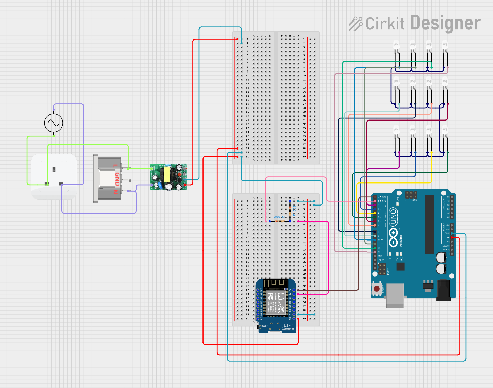
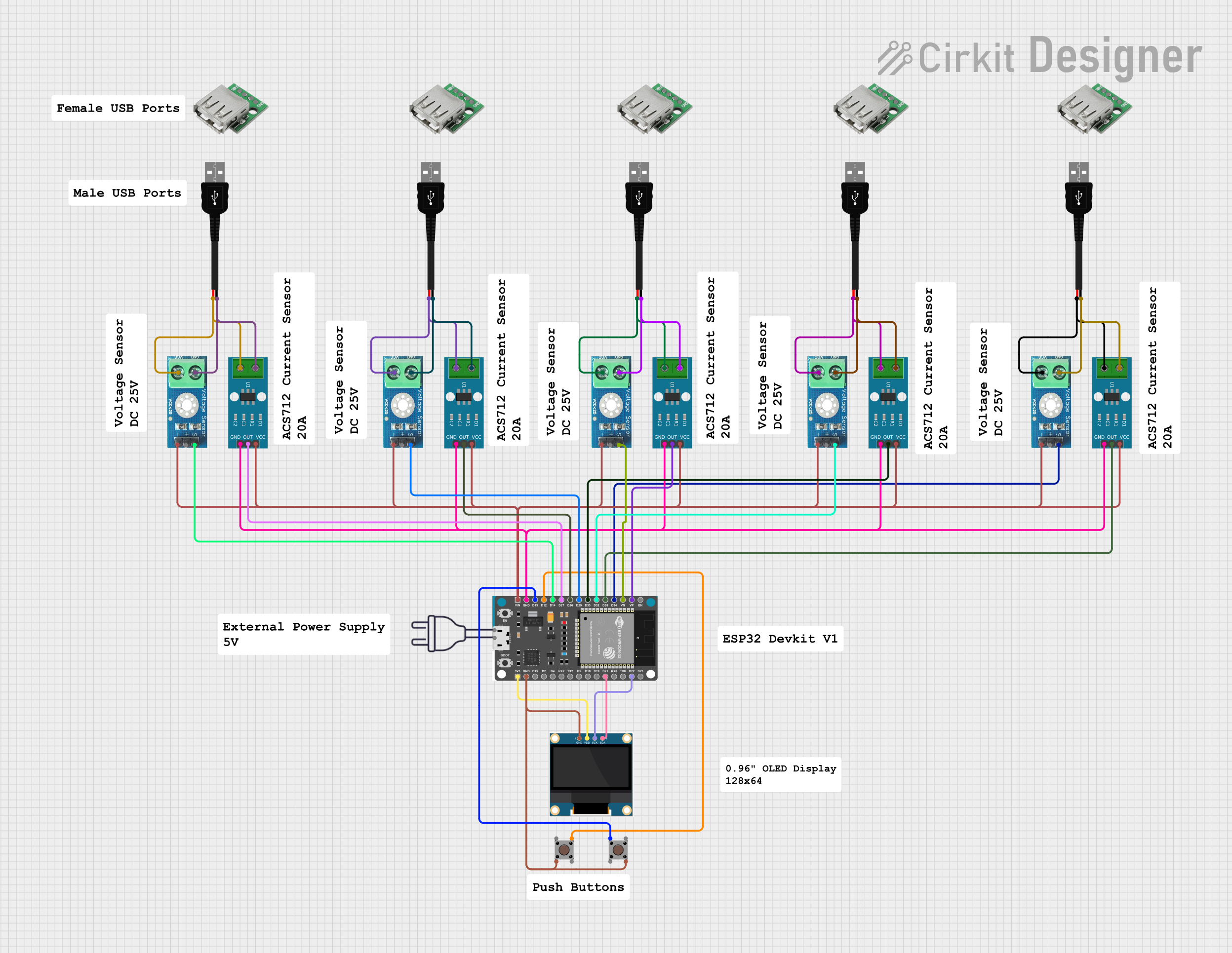

Explore Projects Built with actodc
Technical Specifications
Key Technical Details
- Input Voltage Range (AC): 85VAC to 264VAC
- Output Voltage Range (DC): 5VDC to 48VDC
- Maximum Output Current: 10A
- Efficiency: Up to 90%
- Isolation Voltage: 3000VAC
- Operating Temperature: -40°C to +85°C
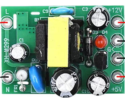
Pin Configuration and Descriptions
| Pin Number | Description | Notes |
|---|---|---|
| 1 | AC Input (Live) | Connect to AC phase |
| 2 | AC Input (Neutral) | Connect to AC neutral |
| 3 | DC Output (+) | Positive DC output |
| 4 | DC Output (-) | Negative DC output |
| 5 | Ground | Connect to system ground |
Usage Instructions
How to Use the ActoDC in a Circuit
Connecting AC Input:
- Connect the AC live wire to pin 1 and the AC neutral wire to pin 2.
- Ensure that the input voltage matches the specifications of the ActoDC.
Connecting DC Output:
- Connect the positive lead of your DC circuit to pin 3.
- Connect the negative lead of your DC circuit to pin 4.
Grounding:
- Connect pin 5 to the system ground to ensure safety and reduce noise.
Important Considerations and Best Practices
- Heat Dissipation: Ensure adequate ventilation around the ActoDC to prevent overheating.
- Overload Protection: Incorporate fuses or circuit breakers to protect against overcurrent conditions.
- Voltage Matching: Verify that the output voltage is suitable for your DC-powered devices.
- Isolation: Maintain proper isolation between the AC input and DC output to prevent electrical shock.
Troubleshooting and FAQs
Common Issues
- Insufficient Output Voltage: Check the AC input voltage and connections.
- Overheating: Ensure proper heat dissipation and verify that the current does not exceed the maximum rating.
- No Output: Verify that the AC input is connected correctly and that there are no open circuits.
Solutions and Tips
- Use a multimeter to check the input and output voltages to ensure they are within the specified range.
- Inspect connections for any loose wires or poor contacts.
- Check the ambient temperature to ensure it is within the operating range.
FAQs
Q: Can the ActoDC be used with any AC voltage? A: The ActoDC can be used with AC voltages within the specified input range of 85VAC to 264VAC.
Q: Is the output voltage adjustable? A: The output voltage range is fixed. Ensure you select the correct model for your required DC output.
Q: What safety precautions should be taken when using the ActoDC? A: Always ensure proper grounding, use appropriate protective devices, and follow electrical codes for safety.
Example Arduino UNO Connection
// Example code to monitor the DC output voltage of the ActoDC actuator
// using an Arduino UNO. This code assumes the use of an analog input to
// measure the DC voltage.

const int analogPin = A0; // Analog input pin that the DC output is connected to
float voltage = 0.0;      // Variable to hold the voltage reading

void setup() {
  Serial.begin(9600); // Start serial communication at 9600 baud
}

void loop() {
  int sensorValue = analogRead(analogPin); // Read the analog input
  voltage = sensorValue * (5.0 / 1023.0);  // Convert the analog reading to voltage
  Serial.print("DC Output Voltage: ");
  Serial.println(voltage); // Print the voltage to the Serial Monitor
  delay(1000);             // Wait for a second before taking another reading
}
Note: The above code is a simple demonstration and assumes that the output voltage of the ActoDC is within the 0-5V range suitable for direct connection to the Arduino's analog input. If the ActoDC's output voltage is higher, a voltage divider or level shifter is required to bring the voltage within the Arduino's input range.