Cirkit Designer
Your all-in-one circuit design IDE
Home /
Component Documentation
How to Use 1 Channel Relay module with Optocoupler: Examples, Pinouts, and Specs
Introduction
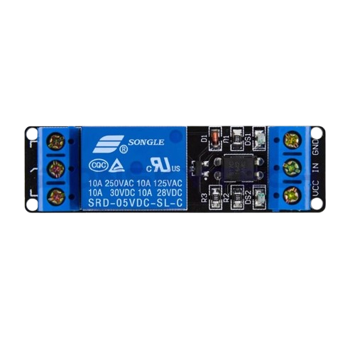
The 1 Channel Relay Module with Optocoupler, manufactured by Songle (Part ID: SRD-05VDC-SL-C), is a versatile electronic component that allows microcontrollers to control high-power devices. This module uses an optocoupler to provide electrical isolation between the control circuit and the high-power load, ensuring safety and reliability.
Explore Projects Built with 1 Channel Relay module with Optocoupler
ESP32-Powered 8-Channel Relay Controller with Wi-Fi Connectivity

This circuit features an ESP32 microcontroller connected to an 8-channel relay module. The ESP32 controls the relay channels via its GPIO pins, allowing for the switching of external devices or loads through the relays.
DC-DC Converter and Relay Module Power Distribution System

This circuit consists of a DC-DC converter powering a 6-channel power module, which in turn supplies 5V to a 2-relay module. The power module distributes the converted voltage to the relay module, enabling it to control external devices.
ESP32-Powered Wi-Fi Controlled 8-Channel Relay Module

This circuit features an ESP32 microcontroller connected to an 8-channel relay module. The ESP32 controls the relay channels via its GPIO pins, allowing it to switch multiple external devices on and off. The ESP32 also provides power to the relay module.
ESP32-POE-ISO Wi-Fi Controlled 4-Channel Relay Module

This circuit features an ESP32-POE-ISO microcontroller connected to a 4-channel 30A 5V relay module. The ESP32 controls the relay channels via its GPIO pins, allowing for the switching of high-power devices through the relay module.
Explore Projects Built with 1 Channel Relay module with Optocoupler
ESP32-Powered 8-Channel Relay Controller with Wi-Fi Connectivity
This circuit features an ESP32 microcontroller connected to an 8-channel relay module. The ESP32 controls the relay channels via its GPIO pins, allowing for the switching of external devices or loads through the relays.
DC-DC Converter and Relay Module Power Distribution System
This circuit consists of a DC-DC converter powering a 6-channel power module, which in turn supplies 5V to a 2-relay module. The power module distributes the converted voltage to the relay module, enabling it to control external devices.
ESP32-Powered Wi-Fi Controlled 8-Channel Relay Module
This circuit features an ESP32 microcontroller connected to an 8-channel relay module. The ESP32 controls the relay channels via its GPIO pins, allowing it to switch multiple external devices on and off. The ESP32 also provides power to the relay module.
ESP32-POE-ISO Wi-Fi Controlled 4-Channel Relay Module
This circuit features an ESP32-POE-ISO microcontroller connected to a 4-channel 30A 5V relay module. The ESP32 controls the relay channels via its GPIO pins, allowing for the switching of high-power devices through the relay module.
Common Applications and Use Cases
- Home Automation: Control lights, fans, and other household appliances.
- Industrial Automation: Manage motors, solenoids, and other industrial equipment.
- Robotics: Operate actuators and other high-power components.
- IoT Projects: Integrate with smart home systems for remote control.
Technical Specifications
Key Technical Details
| Parameter | Value |
|---|---|
| Operating Voltage | 5V DC |
| Trigger Voltage | 0-5V DC |
| Trigger Current | 20mA |
| Relay Type | SPDT (Single Pole Double Throw) |
| Contact Rating | 10A @ 250V AC / 10A @ 30V DC |
| Optocoupler | Yes |
| Dimensions | 50mm x 26mm x 18.5mm |
Pin Configuration and Descriptions
| Pin Name | Description |
|---|---|
| VCC | Connect to 5V DC power supply |
| GND | Connect to ground |
| IN | Control signal from microcontroller (0-5V) |
| NO | Normally Open contact |
| COM | Common contact |
| NC | Normally Closed contact |
Usage Instructions
How to Use the Component in a Circuit
Power the Module:
- Connect the VCC pin to a 5V DC power supply.
- Connect the GND pin to the ground of the power supply.
Control Signal:
- Connect the IN pin to a digital output pin of the microcontroller (e.g., Arduino UNO).
Load Connection:
- Connect the high-power device to the NO (Normally Open) or NC (Normally Closed) and COM (Common) pins based on your requirement.
Important Considerations and Best Practices
- Electrical Isolation: Ensure that the control circuit and the high-power load are electrically isolated to prevent damage to the microcontroller.
- Current Rating: Do not exceed the relay's contact rating of 10A to avoid damage.
- Flyback Diode: Use a flyback diode across inductive loads (e.g., motors) to protect the relay from voltage spikes.
Example Circuit with Arduino UNO
/*
 * Example code to control a 1 Channel Relay Module with Optocoupler
 * using an Arduino UNO. The relay is connected to digital pin 7.
 */

const int relayPin = 7; // Define the relay control pin

void setup() {
  pinMode(relayPin, OUTPUT); // Set the relay pin as an output
  digitalWrite(relayPin, LOW); // Initialize the relay as off
}

void loop() {
  digitalWrite(relayPin, HIGH); // Turn the relay on
  delay(1000); // Wait for 1 second
  digitalWrite(relayPin, LOW); // Turn the relay off
  delay(1000); // Wait for 1 second
}
Troubleshooting and FAQs
Common Issues Users Might Face
Relay Not Switching:
- Solution: Ensure the control signal voltage is within the specified range (0-5V). Check the connections and power supply.
High-Power Device Not Operating:
- Solution: Verify the load connections (NO/NC and COM). Ensure the load does not exceed the relay's contact rating.
Microcontroller Resetting:
- Solution: Ensure proper electrical isolation. Use a separate power supply for the relay module if necessary.
Solutions and Tips for Troubleshooting
- Check Connections: Double-check all connections to ensure they are secure and correct.
- Use Proper Power Supply: Ensure the power supply provides sufficient current for the relay module and the load.
- Debounce Control Signal: If the relay is switching erratically, consider debouncing the control signal in the microcontroller code.
By following this documentation, users can effectively integrate the 1 Channel Relay Module with Optocoupler into their projects, ensuring safe and reliable operation.