Cirkit Designer Logo
Cirkit Designer
Your all-in-one circuit design IDE
Home / 
Component Documentation

How to Use Contactor: Examples, Pinouts, and Specs

Image of Contactor
Cirkit Designer LogoDesign with Contactor in Cirkit Designer

Introduction

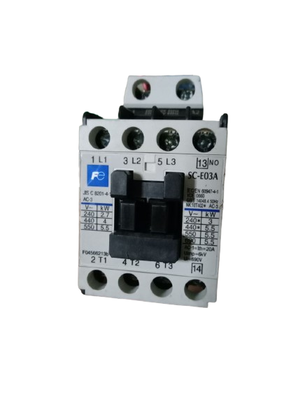
The Fuji SC-E03A Contactor is an electrically-controlled switch designed for switching electrical power circuits. It operates similarly to a relay but is capable of handling higher current ratings, making it suitable for industrial and heavy-duty applications. Contactors are essential components in motor control systems, HVAC systems, lighting control, and other high-power applications.

Explore Projects Built with Contactor

Use Cirkit Designer to design, explore, and prototype these projects online. Some projects support real-time simulation. Click "Open Project" to start designing instantly!
Electromechanical Pump Control Circuit with Emergency Stop
Image of Pelton.: A project utilizing Contactor in a practical application
This circuit is designed to control a pump using a contactor that is manually operated by a switch and can be overridden by an emergency stop. The contactor enables power from an AC power outlet to the pump, and the emergency stop can interrupt the power circuit for safety purposes.
Cirkit Designer LogoOpen Project in Cirkit Designer
Industrial Power Distribution and Safety Control System
Image of Control Diagram: A project utilizing Contactor in a practical application
This circuit is designed for power distribution and safety control in an industrial setting. It features a main isolator and circuit breaker for power management, multiple PSUs for 5V, 12V, and 24V outputs, and a safety relay system that interfaces with E-stop buttons and a start switch to control a main contactor, ensuring safe operation and emergency power cut-off capabilities.
Cirkit Designer LogoOpen Project in Cirkit Designer
Arduino UNO Controlled PIR Motion Sensor with Relay and Contactor for 220V Fan Automation
Image of ultrasonic sensor , relay and aurdino circuit diagram : A project utilizing Contactor in a practical application
This circuit is designed to detect motion using an HC-SR501 PIR motion sensor and control a 220V fan via a magnetic contactor, with an Arduino UNO as the central processing unit. The Arduino is powered by a DC to DC boost converter connected to a 240V power source through a circuit breaker for safety. Upon detection of motion, the Arduino triggers a relay that activates the magnetic contactor, which in turn powers the fan.
Cirkit Designer LogoOpen Project in Cirkit Designer
Battery-Powered Light-Activated Relay Circuit with Photocell and Transistor
Image of darshan: A project utilizing Contactor in a practical application
This circuit is a light-sensitive relay switch that uses a photocell (LDR) to control a 12V relay via a BC547 transistor. The relay is powered by a 12V battery, and the transistor acts as a switch that is triggered by the resistance change in the LDR, which is influenced by the ambient light level.
Cirkit Designer LogoOpen Project in Cirkit Designer

Explore Projects Built with Contactor

Use Cirkit Designer to design, explore, and prototype these projects online. Some projects support real-time simulation. Click "Open Project" to start designing instantly!
Image of Pelton.: A project utilizing Contactor in a practical application
Electromechanical Pump Control Circuit with Emergency Stop
This circuit is designed to control a pump using a contactor that is manually operated by a switch and can be overridden by an emergency stop. The contactor enables power from an AC power outlet to the pump, and the emergency stop can interrupt the power circuit for safety purposes.
Cirkit Designer LogoOpen Project in Cirkit Designer
Image of Control Diagram: A project utilizing Contactor in a practical application
Industrial Power Distribution and Safety Control System
This circuit is designed for power distribution and safety control in an industrial setting. It features a main isolator and circuit breaker for power management, multiple PSUs for 5V, 12V, and 24V outputs, and a safety relay system that interfaces with E-stop buttons and a start switch to control a main contactor, ensuring safe operation and emergency power cut-off capabilities.
Cirkit Designer LogoOpen Project in Cirkit Designer
Image of ultrasonic sensor , relay and aurdino circuit diagram : A project utilizing Contactor in a practical application
Arduino UNO Controlled PIR Motion Sensor with Relay and Contactor for 220V Fan Automation
This circuit is designed to detect motion using an HC-SR501 PIR motion sensor and control a 220V fan via a magnetic contactor, with an Arduino UNO as the central processing unit. The Arduino is powered by a DC to DC boost converter connected to a 240V power source through a circuit breaker for safety. Upon detection of motion, the Arduino triggers a relay that activates the magnetic contactor, which in turn powers the fan.
Cirkit Designer LogoOpen Project in Cirkit Designer
Image of darshan: A project utilizing Contactor in a practical application
Battery-Powered Light-Activated Relay Circuit with Photocell and Transistor
This circuit is a light-sensitive relay switch that uses a photocell (LDR) to control a 12V relay via a BC547 transistor. The relay is powered by a 12V battery, and the transistor acts as a switch that is triggered by the resistance change in the LDR, which is influenced by the ambient light level.
Cirkit Designer LogoOpen Project in Cirkit Designer

Technical Specifications

Key Technical Details

Parameter Value
Manufacturer Fuji Electric
Part ID SC-E03A
Rated Operational Voltage 690V AC
Rated Operational Current 9A
Coil Voltage 24V DC, 48V DC, 110V AC, 220V AC
Power Rating 4 kW (AC-3)
Number of Poles 3
Mechanical Life 10 million operations
Electrical Life 1 million operations

Pin Configuration and Descriptions

Pin Number Pin Name Description
1 L1 Line 1 (Power Input)
2 L2 Line 2 (Power Input)
3 L3 Line 3 (Power Input)
4 T1 Load 1 (Power Output)
5 T2 Load 2 (Power Output)
6 T3 Load 3 (Power Output)
A1 Coil+ Positive terminal of the control coil
A2 Coil- Negative terminal of the control coil

Usage Instructions

How to Use the Component in a Circuit

  1. Power Connections:

    • Connect the power supply lines to the L1, L2, and L3 terminals.
    • Connect the load to the T1, T2, and T3 terminals.
  2. Control Coil:

    • Connect the control voltage to the A1 (positive) and A2 (negative) terminals of the coil.
    • Ensure the control voltage matches the coil voltage rating (e.g., 24V DC, 110V AC).
  3. Activation:

    • When the control voltage is applied to the coil, the contactor will close the circuit between L1-T1, L2-T2, and L3-T3, allowing current to flow to the load.

Important Considerations and Best Practices

  • Voltage and Current Ratings: Ensure that the voltage and current ratings of the contactor match the requirements of your application.
  • Heat Dissipation: Provide adequate ventilation or cooling to prevent overheating, especially in high-power applications.
  • Safety: Always disconnect power before making any connections or modifications to the circuit.
  • Regular Maintenance: Periodically inspect the contactor for signs of wear or damage and replace it if necessary.

Troubleshooting and FAQs

Common Issues and Solutions

  1. Contactor Not Activating:

    • Check Control Voltage: Ensure the control voltage is correctly applied to the coil terminals (A1 and A2).
    • Inspect Connections: Verify that all connections are secure and free from corrosion.
    • Coil Resistance: Measure the resistance of the coil to ensure it is within the specified range.
  2. Excessive Heating:

    • Overload: Ensure the contactor is not overloaded beyond its rated current.
    • Ventilation: Improve ventilation or add cooling to reduce heat buildup.
  3. Intermittent Operation:

    • Loose Connections: Check for loose or intermittent connections in the control circuit.
    • Control Voltage Stability: Ensure the control voltage is stable and within the specified range.

FAQs

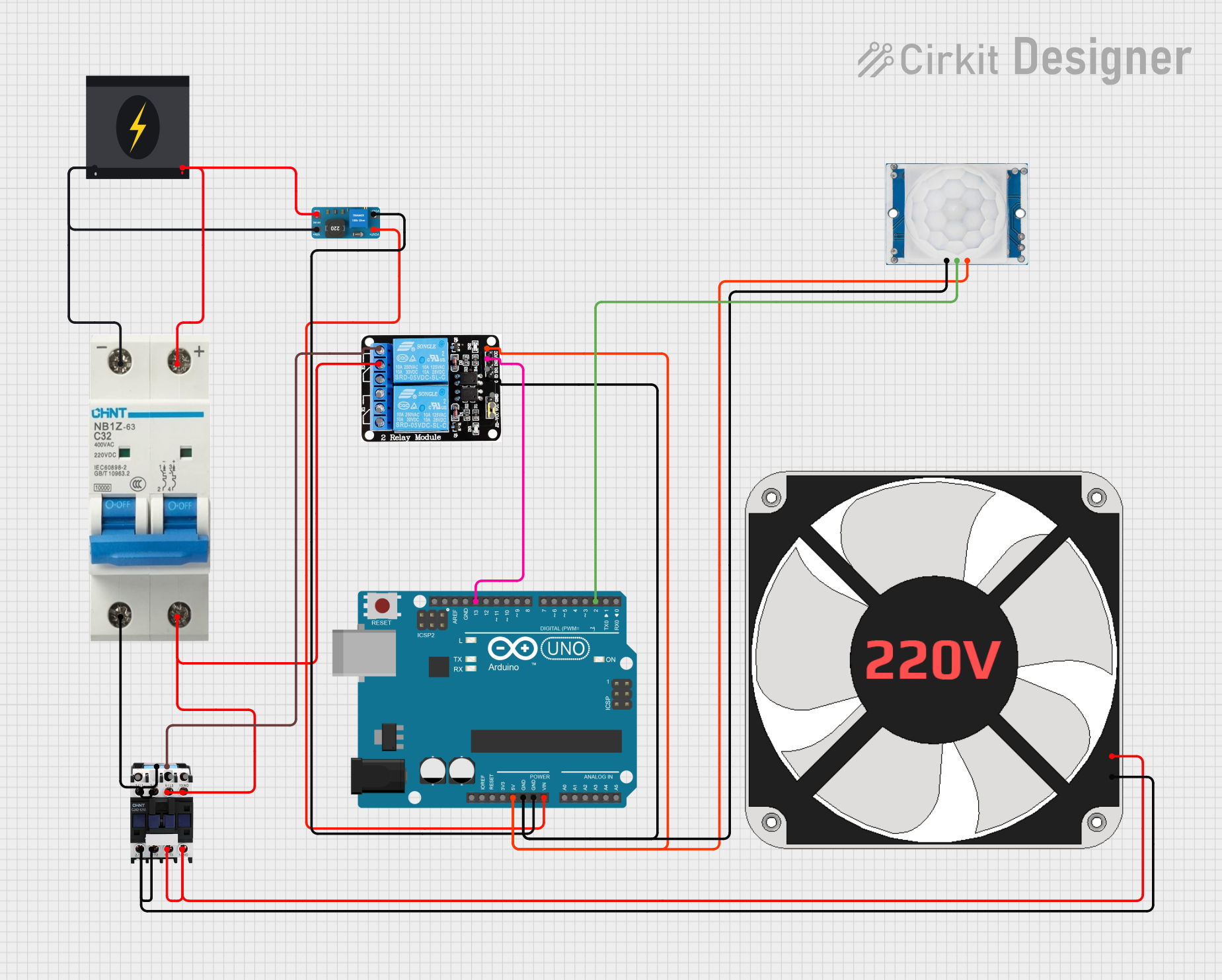
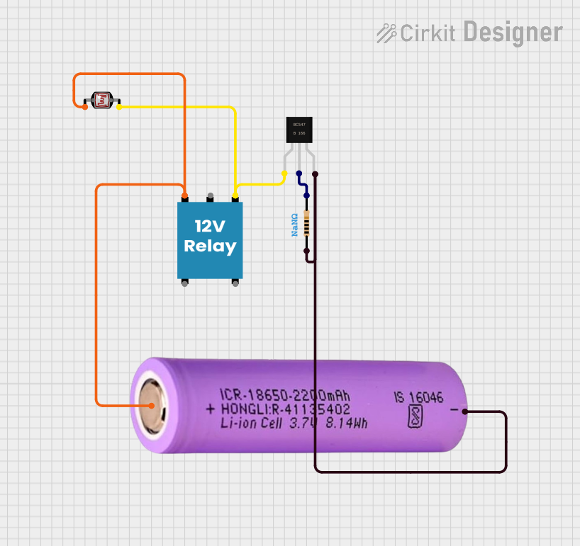
Q: Can the SC-E03A contactor be used with an Arduino UNO? A: Yes, the SC-E03A contactor can be controlled using an Arduino UNO by interfacing it with a relay module or a transistor circuit to handle the control voltage.

Q: What is the difference between a contactor and a relay? A: Contactors are designed for higher current applications and have more robust construction compared to relays, which are typically used for lower current switching.

Q: How do I determine the correct coil voltage for my application? A: The coil voltage should match the control voltage available in your system. Common coil voltages for the SC-E03A include 24V DC, 48V DC, 110V AC, and 220V AC.

Example Code for Arduino UNO

Below is an example code to control the SC-E03A contactor using an Arduino UNO and a relay module:

// Define the pin connected to the relay module
const int relayPin = 7;

void setup() {
  // Initialize the relay pin as an output
  pinMode(relayPin, OUTPUT);
  // Start with the relay off
  digitalWrite(relayPin, LOW);
}

void loop() {
  // Turn the relay on (activate the contactor)
  digitalWrite(relayPin, HIGH);
  delay(5000); // Keep the contactor on for 5 seconds

  // Turn the relay off (deactivate the contactor)
  digitalWrite(relayPin, LOW);
  delay(5000); // Keep the contactor off for 5 seconds
}

In this example, the relay module is connected to pin 7 of the Arduino UNO. The code alternates between turning the relay on and off every 5 seconds, which in turn controls the SC-E03A contactor.

By following this documentation, users can effectively utilize the Fuji SC-E03A contactor in their applications, ensuring reliable and efficient operation.