How to Use M02_BUTTON: Examples, Pinouts, and Specs
Introduction
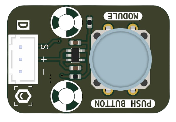
The M02_BUTTON is a momentary push-button switch manufactured by MakerEdu.vn (Part ID: BUTTON). This component is designed to complete an electrical circuit when pressed and break the circuit when released. It is widely used for user input in electronic devices, such as triggering actions, resetting systems, or navigating menus. Its compact design and ease of use make it a staple in both beginner and advanced electronics projects.
Explore Projects Built with M02_BUTTON

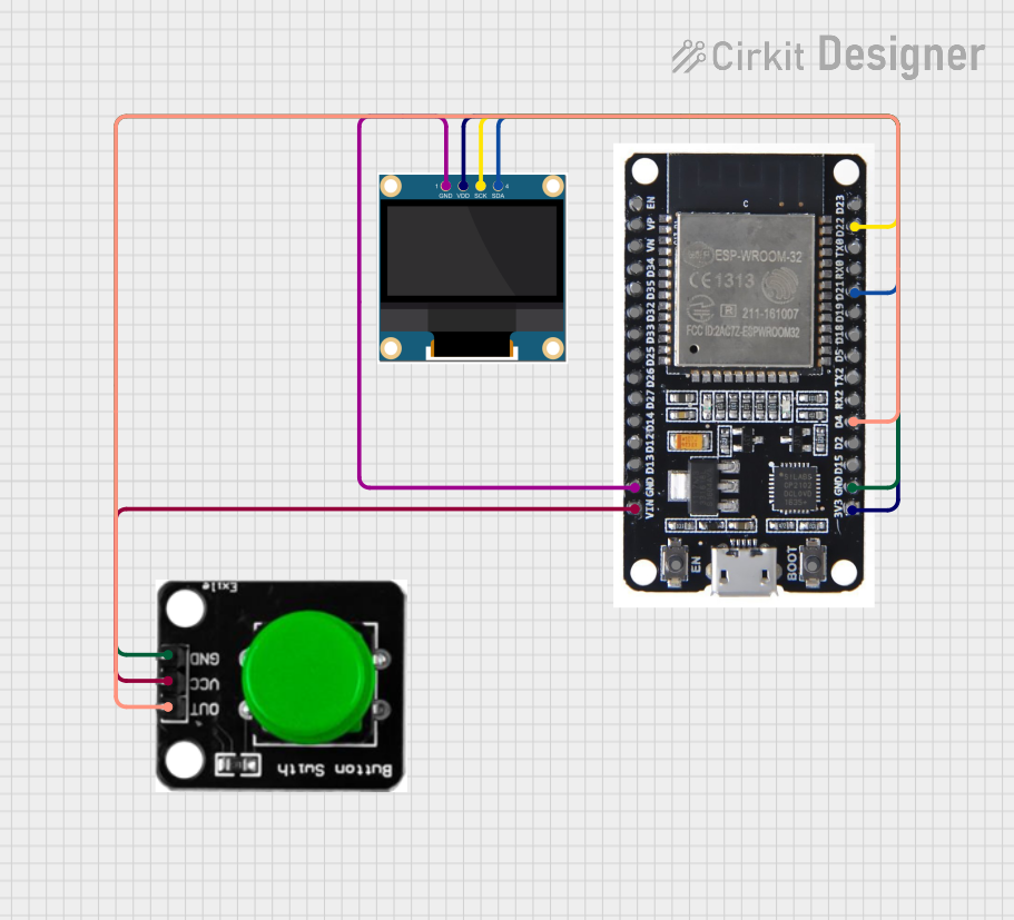
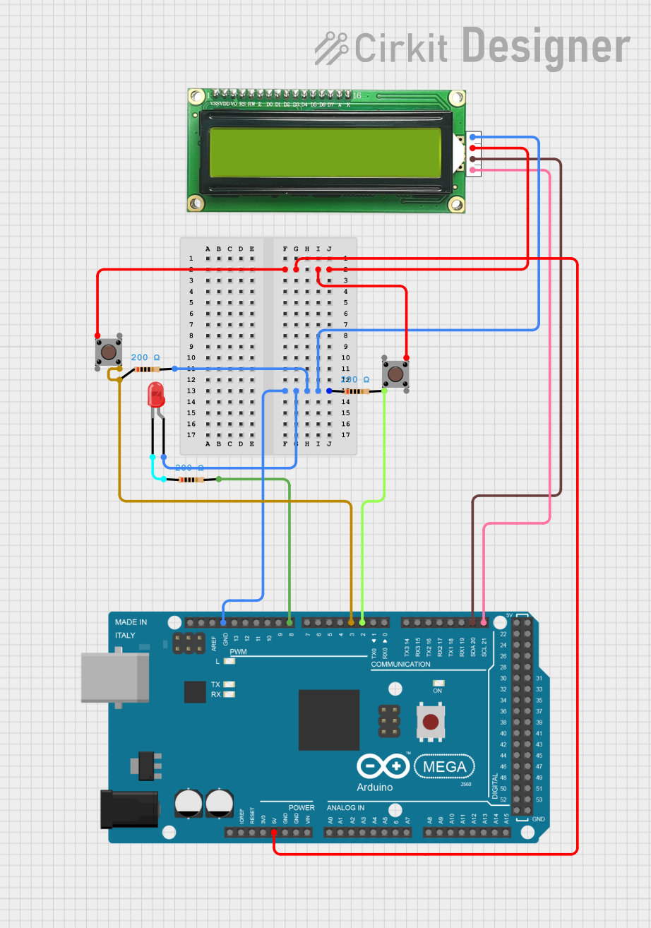
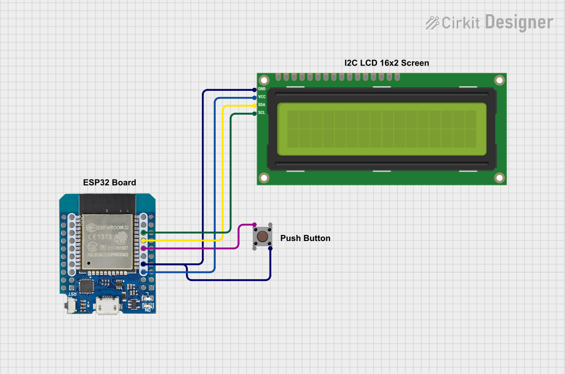
Explore Projects Built with M02_BUTTON
Common Applications
- User input for microcontroller-based systems (e.g., Arduino, Raspberry Pi)
- Reset buttons for electronic devices
- Mode selection or menu navigation
- Prototyping and DIY electronics projects
Technical Specifications
The following table outlines the key technical details of the M02_BUTTON:
| Parameter | Value |
|---|---|
| Manufacturer | MakerEdu.vn |
| Part ID | BUTTON |
| Type | Momentary push-button switch |
| Operating Voltage | 3.3V to 5V |
| Maximum Current | 50mA |
| Contact Resistance | ≤ 100mΩ |
| Insulation Resistance | ≥ 100MΩ |
| Operating Temperature | -20°C to +70°C |
| Dimensions | 6mm x 6mm x 5mm |
| Mounting Type | Through-hole or PCB mount |
Pin Configuration
The M02_BUTTON has four pins, but only two are electrically active. The other two pins are for mechanical stability. Below is the pin configuration:
| Pin Number | Description |
|---|---|
| Pin 1 | Active terminal (connect to circuit) |
| Pin 2 | Active terminal (connect to circuit) |
| Pin 3 | Mechanical support (no connection) |
| Pin 4 | Mechanical support (no connection) |
Usage Instructions
How to Use the M02_BUTTON in a Circuit
- Identify the Active Pins: Use a multimeter to identify the two active pins. These pins will show continuity when the button is pressed.
- Connect to Circuit:
- Connect one active pin to the input signal or microcontroller pin.
- Connect the other active pin to ground (GND) or a pull-down resistor.
- Debounce the Button: To avoid false triggering due to mechanical bouncing, use a hardware debounce circuit (e.g., a capacitor) or implement software debouncing in your code.
- Test the Circuit: Verify the button's functionality by pressing it and observing the circuit's response.
Important Considerations
- Pull-up or Pull-down Resistors: Always use a pull-up or pull-down resistor to ensure a stable signal when the button is not pressed.
- Voltage and Current Ratings: Do not exceed the specified voltage (5V) or current (50mA) to avoid damaging the button.
- Mounting: Ensure the button is securely mounted on the PCB or breadboard to prevent loose connections.
Example: Using M02_BUTTON with Arduino UNO
Below is an example of how to use the M02_BUTTON with an Arduino UNO to toggle an LED:
// Define pin connections
const int buttonPin = 2;  // Pin connected to the button
const int ledPin = 13;    // Pin connected to the LED

// Variable to store button state
int buttonState = 0;

void setup() {
  pinMode(buttonPin, INPUT_PULLUP); // Set button pin as input with internal pull-up
  pinMode(ledPin, OUTPUT);         // Set LED pin as output
}

void loop() {
  buttonState = digitalRead(buttonPin); // Read the button state

  if (buttonState == LOW) { // Button is pressed (LOW due to pull-up resistor)
    digitalWrite(ledPin, HIGH); // Turn on the LED
  } else {
    digitalWrite(ledPin, LOW);  // Turn off the LED
  }
}
Note: The internal pull-up resistor is enabled in the code to simplify the circuit.
Troubleshooting and FAQs
Common Issues
Button Not Responding
- Cause: Incorrect pin connections or loose wiring.
- Solution: Verify the active pins using a multimeter and ensure secure connections.
False Triggering
- Cause: Mechanical bouncing of the button.
- Solution: Add a hardware debounce circuit (e.g., a 0.1µF capacitor across the active pins) or implement software debouncing.
Button Stuck or Not Clicking
- Cause: Physical damage or debris inside the button.
- Solution: Replace the button or clean it carefully if possible.
FAQs
Q: Can I use the M02_BUTTON with 12V circuits?
A: No, the M02_BUTTON is rated for a maximum of 5V. Using it with higher voltages may damage the component.
Q: How do I debounce the button in software?
A: You can use a delay or a state-checking algorithm in your code to filter out rapid changes in the button state caused by bouncing.
Q: Are all four pins of the button functional?
A: No, only two pins are electrically active. The other two pins are for mechanical stability.
By following this documentation, you can effectively integrate the M02_BUTTON into your electronic projects.