How to Use DAC AD5627: Examples, Pinouts, and Specs
Introduction
The AD5627 is a 12-bit digital-to-analog converter (DAC) manufactured by Analog Devices. It is designed to deliver high accuracy and low power consumption, making it ideal for a wide range of applications. The device features a serial interface, which simplifies integration into digital systems. Its compact design and robust performance make it suitable for industrial control, instrumentation, audio systems, and other precision applications.
Explore Projects Built with DAC AD5627

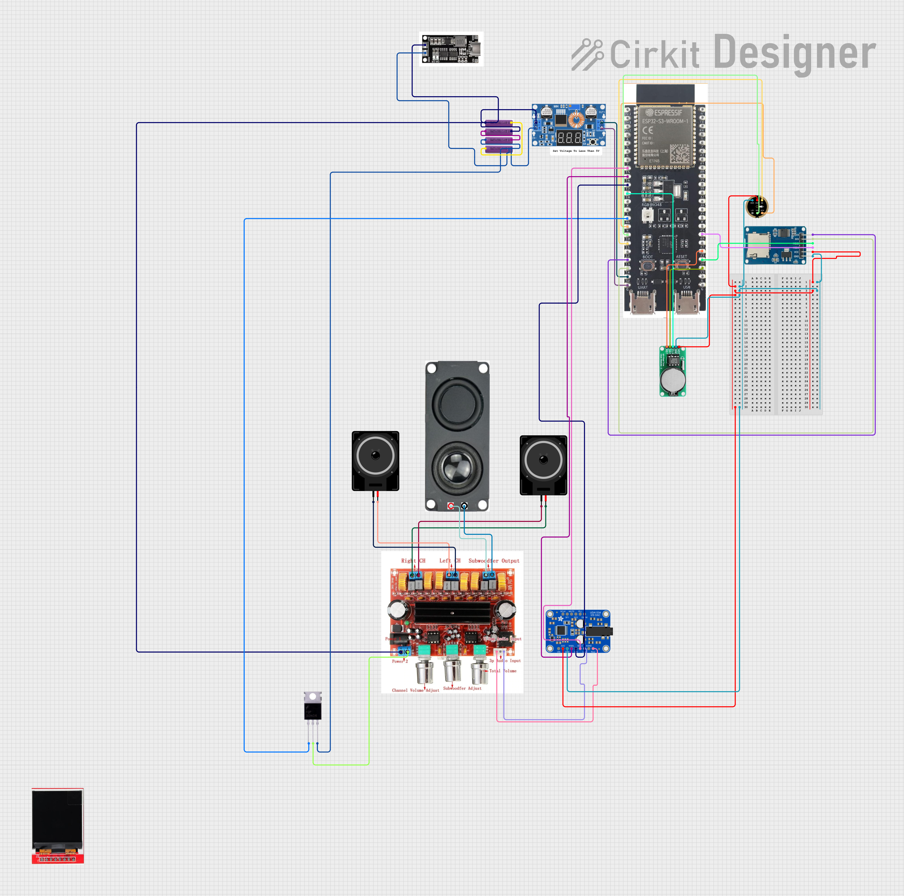
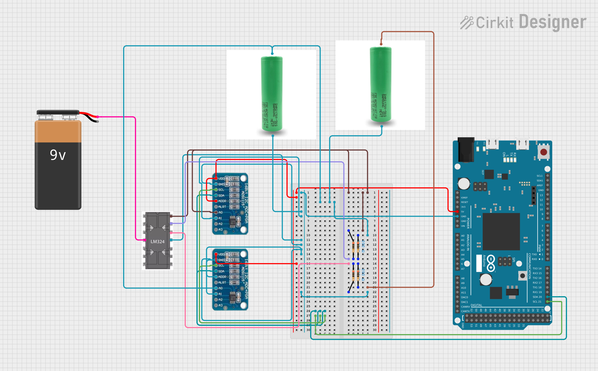

Explore Projects Built with DAC AD5627
Common Applications:
- Industrial process control
- Data acquisition systems
- Portable instrumentation
- Audio signal generation
- Programmable voltage sources
Technical Specifications
Key Technical Details:
- Resolution: 12 bits
- Supply Voltage: 2.7 V to 5.5 V
- Power Consumption: 0.7 mW at 3 V
- Output Voltage Range: 0 V to VREF
- Reference Input: External reference (up to 5.5 V)
- Interface: I²C-compatible serial interface
- Operating Temperature Range: −40°C to +125°C
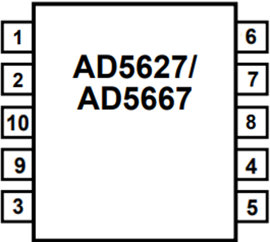
- Package: 10-lead MSOP (AD5627BRMZ)
Pin Configuration and Descriptions:
The AD5627 is available in a 10-lead MSOP package. The pin configuration and descriptions are as follows:
| Pin Number | Pin Name | Description |
|---|---|---|
| 1 | VDD | Positive power supply (2.7 V to 5.5 V). |
| 2 | GND | Ground reference for the device. |
| 3 | SDA | Serial data line for I²C communication. |
| 4 | SCL | Serial clock line for I²C communication. |
| 5 | LDAC | Load DAC input (active low). Updates the DAC output when asserted. |
| 6 | A0 | Address pin 0 for I²C device address selection. |
| 7 | A1 | Address pin 1 for I²C device address selection. |
| 8 | VOUT | Analog output voltage from the DAC. |
| 9 | VREF | External reference voltage input. |
| 10 | RESET | Active low reset pin. Resets the DAC output to zero or mid-scale (configurable). |
Usage Instructions
How to Use the AD5627 in a Circuit:
- Power Supply: Connect the VDD pin to a stable power supply (2.7 V to 5.5 V) and the GND pin to the ground.
- Reference Voltage: Provide an external reference voltage to the VREF pin. The output voltage range will be 0 V to VREF.
- I²C Communication:
- Connect the SDA and SCL pins to the corresponding I²C lines of the microcontroller.
- Use pull-up resistors (typically 4.7 kΩ) on the SDA and SCL lines.
- Address Selection: Configure the A0 and A1 pins to set the I²C address of the device. This allows multiple AD5627 devices to share the same I²C bus.
- Output Voltage: The DAC output voltage is available on the VOUT pin. Use the LDAC pin to control when the output is updated.
- Reset Functionality: Use the RESET pin to reset the DAC output to zero or mid-scale, depending on the configuration.
Example Code for Arduino UNO:
Below is an example of how to interface the AD5627 with an Arduino UNO using the Wire library for I²C communication.
#include <Wire.h>

// Define the I²C address of the AD5627 (example: A0 = 0, A1 = 0)
#define AD5627_I2C_ADDRESS 0x0C

void setup() {
  Wire.begin(); // Initialize I²C communication
  Serial.begin(9600); // Initialize serial communication for debugging
  Serial.println("AD5627 DAC Example");
}

void loop() {
  uint16_t dacValue = 2048; // Example: Set DAC output to mid-scale (12-bit value)

  // Send the DAC value to the AD5627
  Wire.beginTransmission(AD5627_I2C_ADDRESS);
  Wire.write((dacValue >> 8) & 0xFF); // Send the upper 8 bits of the 12-bit value
  Wire.write(dacValue & 0xFF);        // Send the lower 8 bits of the 12-bit value
  Wire.endTransmission();

  Serial.println("DAC value updated");
  delay(1000); // Wait for 1 second before updating again
}
Important Considerations:
- Ensure that the reference voltage (VREF) is stable and within the specified range.
- Use appropriate pull-up resistors on the I²C lines (SDA and SCL).
- Avoid exceeding the maximum voltage ratings to prevent damage to the device.
- Configure the I²C address correctly if multiple devices are used on the same bus.
Troubleshooting and FAQs
Common Issues and Solutions:
No Output Voltage on VOUT:
- Verify that the power supply (VDD) and ground (GND) connections are correct.
- Ensure that the reference voltage (VREF) is applied and within the specified range.
- Check the I²C communication for errors (e.g., incorrect address or wiring).
I²C Communication Fails:
- Confirm that the SDA and SCL lines are connected properly.
- Use pull-up resistors on the SDA and SCL lines.
- Verify the I²C address configuration using the A0 and A1 pins.
Incorrect Output Voltage:
- Ensure that the DAC value sent via I²C is correct.
- Check for noise or instability in the reference voltage (VREF).
FAQs:
Q1: Can the AD5627 operate without an external reference voltage?
A1: No, the AD5627 requires an external reference voltage on the VREF pin to generate the output voltage.
Q2: How many AD5627 devices can be connected to the same I²C bus?
A2: Up to four devices can be connected by configuring the A0 and A1 address pins.
Q3: What happens if the RESET pin is asserted?
A3: The DAC output will reset to zero or mid-scale, depending on the configuration.
Q4: Is the AD5627 suitable for audio applications?
A4: Yes, the AD5627's high resolution and low power consumption make it suitable for audio signal generation.