How to Use XT60 Connector: Examples, Pinouts, and Specs
Introduction
The XT60 connector is a high-current, polarized connector widely used in RC (radio-controlled) applications, such as drones, RC cars, and airplanes. Its robust design ensures secure and reliable connections, making it ideal for high-power systems. The XT60 connector is made from durable nylon and features gold-plated pins, which provide excellent conductivity and resistance to wear. Its compact size and ease of use make it a popular choice for hobbyists and professionals alike.
Explore Projects Built with XT60 Connector


Explore Projects Built with XT60 Connector
Common Applications
- RC vehicles (drones, cars, airplanes, boats)
- Lithium Polymer (LiPo) battery connections
- High-current power systems
- DIY electronics projects requiring secure power delivery
Technical Specifications
The XT60 connector is designed to handle high currents while maintaining a compact and lightweight form factor. Below are its key technical details:
| Parameter | Specification |
|---|---|
| Rated Current | 60A continuous (up to 100A peak) |
| Voltage Rating | Up to 500V DC |
| Contact Material | Gold-plated brass |
| Housing Material | Nylon (heat-resistant up to 260°C) |
| Connector Type | Male and Female (polarized) |
| Wire Gauge Support | 12 AWG to 10 AWG |
| Dimensions (assembled) | 21.5mm x 15mm x 8mm |
| Weight (per pair) | ~7.72g |
Pin Configuration and Descriptions
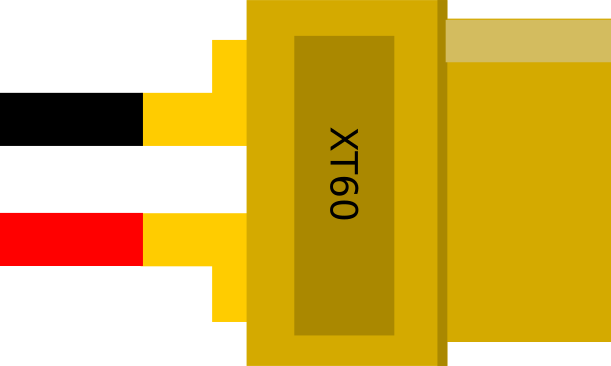
The XT60 connector consists of two gold-plated pins housed in a yellow nylon shell. The pins are polarized to prevent reverse polarity connections. Below is the pin configuration:
| Pin | Description | Polarity |
|---|---|---|
| 1 | Positive terminal (+) | Positive |
| 2 | Negative terminal (-) | Negative |
The male connector has exposed pins, while the female connector has recessed sockets to ensure safe handling and prevent accidental short circuits.
Usage Instructions
How to Use the XT60 Connector in a Circuit
- Prepare the Wires: Strip the insulation from the ends of the wires you intend to connect. Ensure the wire gauge is compatible (12 AWG to 10 AWG is recommended).
- Tin the Wires: Apply solder to the exposed wire ends to make them easier to connect to the XT60 pins.
- Solder the Wires to the Connector:
- Heat the solder cup of the XT60 pin with a soldering iron.
- Insert the tinned wire into the solder cup and apply solder until the connection is secure.
- Repeat for both the positive and negative terminals.
- Assemble the Connector: Once the wires are soldered, slide any heat shrink tubing over the connections and shrink it using a heat gun for insulation.
- Test the Connection: Use a multimeter to verify the polarity and continuity of the connection before use.
Important Considerations and Best Practices
- Polarity: Always double-check the polarity of the connections to avoid damaging your components.
- Heat Management: Use a soldering iron with sufficient power (at least 60W) to ensure quick and clean soldering without overheating the connector.
- Secure Connections: Ensure the wires are firmly soldered to the pins to prevent loose connections, which can lead to overheating or power loss.
- Avoid Overcurrent: Do not exceed the rated current of 60A continuous to prevent damage to the connector or the circuit.
Example: Connecting an XT60 to an Arduino UNO
While the XT60 connector is not directly compatible with the Arduino UNO, it can be used to supply power to the Arduino through a voltage regulator. Below is an example of how to connect an XT60-powered LiPo battery to an Arduino UNO using a 5V voltage regulator module.
Circuit Diagram
- Connect the XT60 connector to the input of the voltage regulator module.
- Connect the output of the voltage regulator (5V and GND) to the Arduino UNO's 5V and GND pins.
Sample Code
// Example code to blink an LED on pin 13 of the Arduino UNO
// Ensure the Arduino is powered via the XT60 connector and voltage regulator

void setup() {
  pinMode(13, OUTPUT); // Set pin 13 as an output
}

void loop() {
  digitalWrite(13, HIGH); // Turn the LED on
  delay(1000);            // Wait for 1 second
  digitalWrite(13, LOW);  // Turn the LED off
  delay(1000);            // Wait for 1 second
}
Troubleshooting and FAQs
Common Issues and Solutions
Loose Connections:
- Issue: The wires are not securely attached to the XT60 pins.
- Solution: Re-solder the wires, ensuring they are fully inserted into the solder cups and the solder flows evenly.
Overheating:
- Issue: The connector becomes hot during use.
- Solution: Check for loose connections or excessive current draw. Ensure the current does not exceed 60A continuous.
Reverse Polarity:
- Issue: The device does not power on or is damaged.
- Solution: Verify the polarity of the connections using a multimeter before powering the circuit.
Difficulty Soldering:
- Issue: The solder does not adhere to the pins or wires.
- Solution: Use a higher-power soldering iron (60W or more) and ensure the pins and wires are clean and pre-tinned.
FAQs
Q: Can I use the XT60 connector for AC applications?
A: No, the XT60 connector is designed for DC applications only and is not suitable for AC power.
Q: Is the XT60 connector waterproof?
A: No, the XT60 connector is not waterproof. If used in wet environments, additional waterproofing measures are required.
Q: Can I connect multiple XT60 connectors in parallel?
A: Yes, but ensure the total current does not exceed the rated capacity of the connectors and wires.
Q: How do I disconnect the XT60 connector safely?
A: Hold the connector housing (not the wires) and pull gently. Avoid pulling on the wires to prevent damage.