How to Use Safety Control Unit: Examples, Pinouts, and Specs
Introduction
The Safety Control Unit (SF-C21), manufactured by Panasonic, is a compact and reliable device designed to monitor and control safety functions in electrical circuits. It ensures that operations remain within safe parameters, preventing accidents, equipment damage, or hazardous conditions. This unit is widely used in industrial automation, machinery safety systems, and other applications requiring stringent safety compliance.
Explore Projects Built with Safety Control Unit

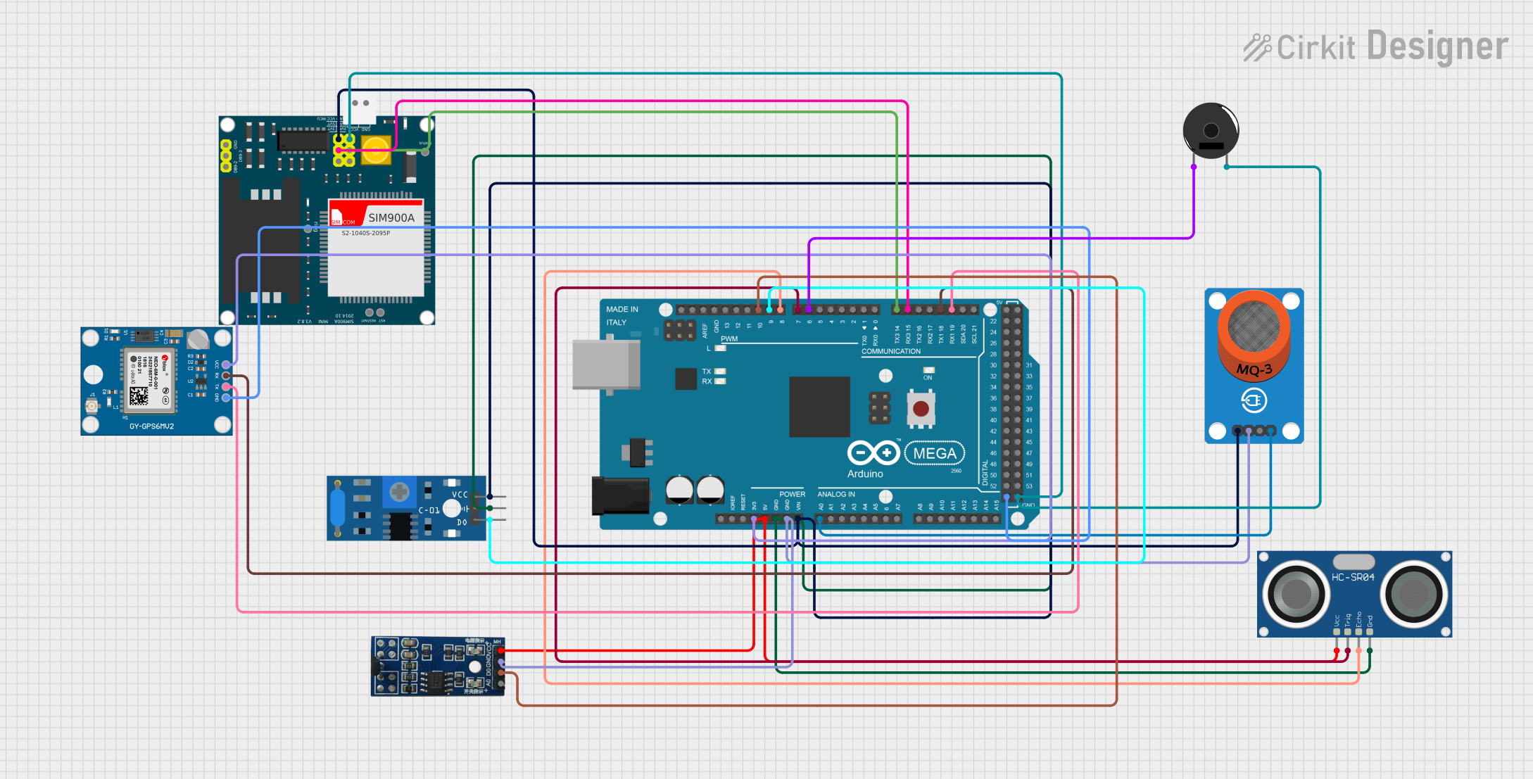
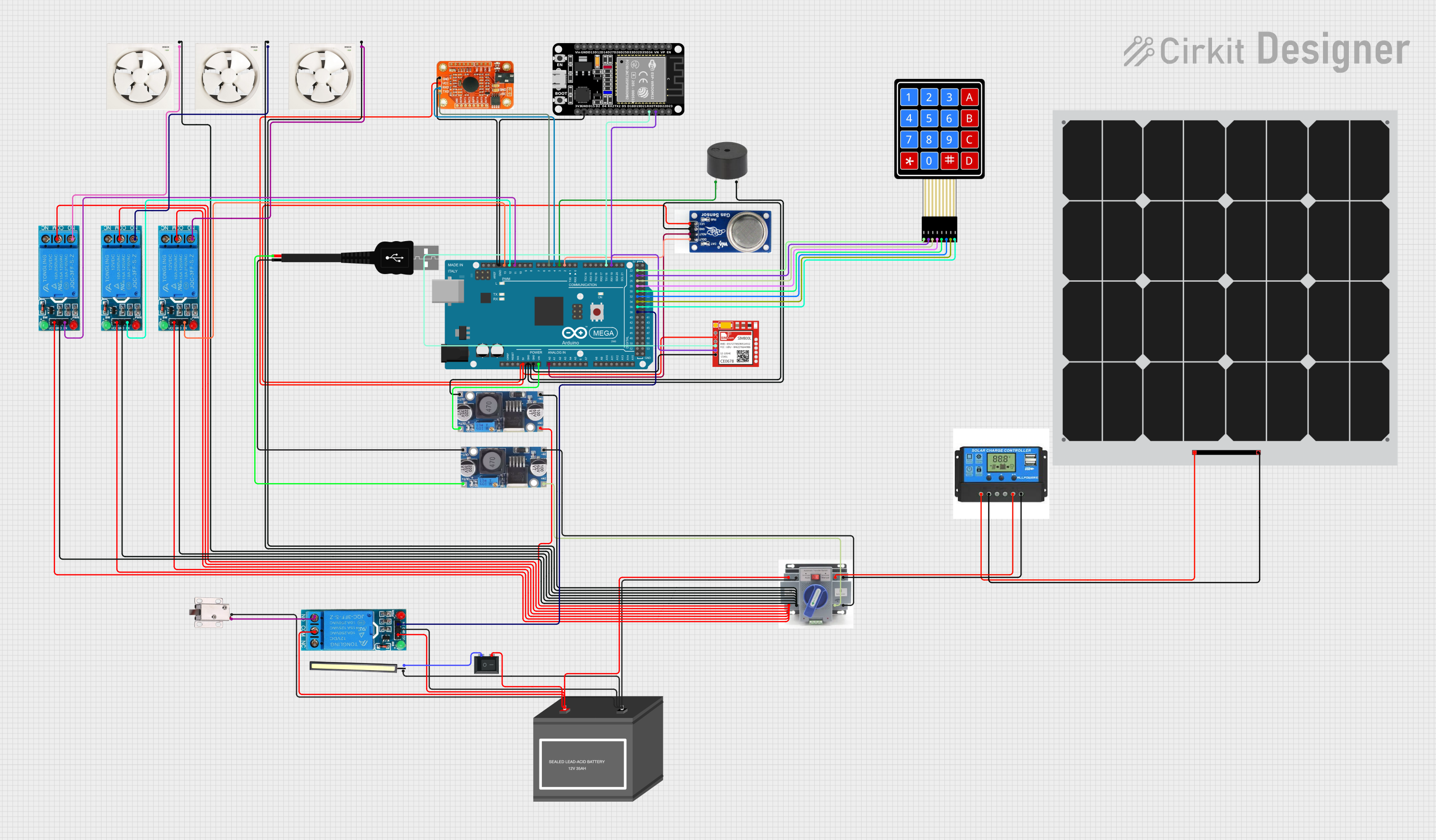

Explore Projects Built with Safety Control Unit
Common Applications and Use Cases
- Industrial machinery safety monitoring
- Emergency stop (E-Stop) systems
- Light curtain and safety sensor integration
- Conveyor belt safety control
- Robotics safety systems
- Compliance with safety standards such as ISO 13849-1 and IEC 61508
Technical Specifications
Key Technical Details
| Parameter | Value |
|---|---|
| Manufacturer | Panasonic |
| Part Number | SF-C21 |
| Power Supply Voltage | 24 V DC ±10% |
| Power Consumption | Max. 2.5 W |
| Safety Inputs | 2 dual-channel inputs |
| Safety Outputs | 2 PNP transistor outputs |
| Response Time | ≤ 10 ms |
| Operating Temperature | -10°C to +55°C |
| Storage Temperature | -20°C to +70°C |
| Dimensions (W x H x D) | 22.5 mm x 99 mm x 114.5 mm |
| Mounting | DIN rail |
| Certifications | CE, UL, TÜV, EN ISO 13849-1 (PLe) |
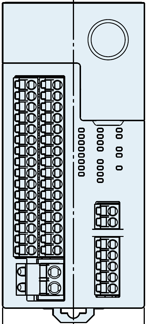
Pin Configuration and Descriptions
The SF-C21 features a terminal block for wiring. Below is the pin configuration:
Input Terminals
| Pin Number | Label | Description |
|---|---|---|
| 1 | S11 | Safety input 1 (channel A) |
| 2 | S12 | Safety input 1 (channel B) |
| 3 | S21 | Safety input 2 (channel A) |
| 4 | S22 | Safety input 2 (channel B) |
Output Terminals
| Pin Number | Label | Description |
|---|---|---|
| 13 | Y1 | Safety output 1 (PNP transistor) |
| 14 | Y2 | Safety output 2 (PNP transistor) |
Power and Ground
| Pin Number | Label | Description |
|---|---|---|
| 24 | +24V | Power supply input (24 V DC) |
| 25 | 0V | Ground (0 V) |
Usage Instructions
How to Use the Component in a Circuit
- Power Supply Connection: Connect the +24V terminal to a regulated 24 V DC power supply and the 0V terminal to ground.
- Safety Inputs: Wire the safety devices (e.g., emergency stop buttons, light curtains) to the input terminals (S11, S12, S21, S22). Ensure proper dual-channel wiring for redundancy.
- Safety Outputs: Connect the safety outputs (Y1, Y2) to the control circuit or actuators that need to be controlled based on safety conditions.
- Mounting: Secure the SF-C21 to a DIN rail in a control panel for stable operation.
- Testing: After wiring, test the system to ensure the safety functions operate as intended.
Important Considerations and Best Practices
- Always follow the wiring diagram provided in the manufacturer's datasheet.
- Use shielded cables for input and output connections to minimize electrical noise.
- Ensure the power supply is stable and within the specified voltage range.
- Regularly inspect and test the safety system to ensure compliance with safety standards.
- Avoid exposing the unit to extreme temperatures, moisture, or vibration.
Example: Connecting to an Arduino UNO
The SF-C21 can be interfaced with an Arduino UNO to monitor safety outputs. Below is an example code snippet:
// Example: Reading safety output signals from SF-C21 using Arduino UNO

const int safetyOutput1 = 2; // Pin connected to Y1 (safety output 1)
const int safetyOutput2 = 3; // Pin connected to Y2 (safety output 2)

void setup() {
  pinMode(safetyOutput1, INPUT); // Set pin 2 as input
  pinMode(safetyOutput2, INPUT); // Set pin 3 as input
  Serial.begin(9600); // Initialize serial communication
}

void loop() {
  int status1 = digitalRead(safetyOutput1); // Read safety output 1
  int status2 = digitalRead(safetyOutput2); // Read safety output 2

  // Print the status of safety outputs
  Serial.print("Safety Output 1: ");
  Serial.println(status1 == HIGH ? "Active" : "Inactive");
  Serial.print("Safety Output 2: ");
  Serial.println(status2 == HIGH ? "Active" : "Inactive");

  delay(500); // Wait for 500 ms before the next reading
}
Notes:
- Use pull-down resistors if necessary to ensure stable readings on the Arduino inputs.
- The safety outputs (Y1, Y2) are PNP transistor outputs, so ensure proper interfacing with the Arduino.
Troubleshooting and FAQs
Common Issues and Solutions
The unit does not power on:
- Verify that the power supply voltage is within the specified range (24 V DC ±10%).
- Check the wiring for loose or incorrect connections.
Safety outputs are not activating:
- Ensure the safety inputs are correctly wired and functioning.
- Verify that the connected safety devices (e.g., E-Stop) are in their normal operating state.
Frequent false triggers:
- Use shielded cables to reduce electrical noise.
- Check for proper grounding of the system.
Response time is too slow:
- Ensure the total response time of the system (including connected devices) meets your application requirements.
FAQs
Q: Can the SF-C21 be used with AC power supplies?
A: No, the SF-C21 is designed to operate with a 24 V DC power supply only.
Q: What safety standards does the SF-C21 comply with?
A: The SF-C21 complies with ISO 13849-1 (PLe) and IEC 61508 standards.
Q: Can I use the SF-C21 in outdoor environments?
A: The SF-C21 is not rated for outdoor use. It should be installed in a protected control panel.
Q: How often should the safety system be tested?
A: Regular testing is recommended, typically as part of routine maintenance or as required by safety regulations.