Cirkit Designer Logo
Cirkit Designer
Your all-in-one circuit design IDE
Home / 
Component Documentation

How to Use 3x4 Phone-Style Matrix Keypad with 12 Buttons 1824: Examples, Pinouts, and Specs

Image of 3x4 Phone-Style Matrix Keypad with 12 Buttons 1824
Cirkit Designer LogoDesign with 3x4 Phone-Style Matrix Keypad with 12 Buttons 1824 in Cirkit Designer

Introduction

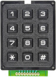
The 3x4 Phone-Style Matrix Keypad (Adafruit Art.-Nr.: AF1824) is a compact and versatile input device featuring 12 buttons arranged in a 3x4 grid layout. This keypad is commonly used for user input in electronic devices, allowing for efficient data entry. It is ideal for applications such as security systems, home automation, and control interfaces. The keypad operates as a matrix, where rows and columns are scanned to detect button presses, making it a cost-effective and space-saving solution.

Explore Projects Built with 3x4 Phone-Style Matrix Keypad with 12 Buttons 1824

Use Cirkit Designer to design, explore, and prototype these projects online. Some projects support real-time simulation. Click "Open Project" to start designing instantly!
Arduino UNO-Based Interactive LED Game with 8x8 Matrix and TM1637 Display
Image of Gra_na_refleks: A project utilizing 3x4 Phone-Style Matrix Keypad with 12 Buttons 1824 in a practical application
This circuit is a game system controlled by an Arduino UNO, featuring an 8x8 LED matrix, a 4x4 keypad, and a TM1637 4-digit display. The user interacts with the game via the keypad, and the game state is displayed on the LED matrix and the TM1637 display, with power supplied by a 9V battery.
Cirkit Designer LogoOpen Project in Cirkit Designer
Arduino UNO Keypad-Controlled LED and Buzzer System with RTC and Bluetooth
Image of Uni: A project utilizing 3x4 Phone-Style Matrix Keypad with 12 Buttons 1824 in a practical application
This circuit is an Arduino-based keypad interface system that reads input from a 4x4 membrane matrix keypad and displays the pressed key on the serial monitor. It also includes a real-time clock (RTC) module, a Bluetooth module, and visual indicators using red and green LEDs. Additionally, a buzzer is controlled via an NPN transistor for audio feedback.
Cirkit Designer LogoOpen Project in Cirkit Designer
Arduino Mega 2560-Based Smart Home Control System with LCD Display and Flame Sensor
Image of Copy of schoolproject (1): A project utilizing 3x4 Phone-Style Matrix Keypad with 12 Buttons 1824 in a practical application
This circuit is a multi-functional embedded system featuring an Arduino Mega 2560 microcontroller that interfaces with a 4x4 membrane keypad, a 20x4 I2C LCD, an 8x8 LED matrix, a DS3231 RTC module, a passive buzzer, and a KY-026 flame sensor. The system is powered by a 5V PSU and is designed to provide real-time clock functionality, user input via the keypad, visual output on the LCD and LED matrix, and flame detection with an audible alert.
Cirkit Designer LogoOpen Project in Cirkit Designer
Arduino UNO Based NFC Reader with Membrane Keypad Interface
Image of NFC_serial: A project utilizing 3x4 Phone-Style Matrix Keypad with 12 Buttons 1824 in a practical application
This circuit features an Arduino UNO connected to a 4x4 membrane matrix keypad, an NFC/RFID reader, and powered by a 9V battery. The Arduino is programmed to detect and display keypad inputs and read NFC tags, likely for an access control or identification system. The NFC/RFID reader communicates with the Arduino via I2C (using SDA and SCL lines), and the keypad is interfaced using digital IO pins.
Cirkit Designer LogoOpen Project in Cirkit Designer

Explore Projects Built with 3x4 Phone-Style Matrix Keypad with 12 Buttons 1824

Use Cirkit Designer to design, explore, and prototype these projects online. Some projects support real-time simulation. Click "Open Project" to start designing instantly!
Image of Gra_na_refleks: A project utilizing 3x4 Phone-Style Matrix Keypad with 12 Buttons 1824 in a practical application
Arduino UNO-Based Interactive LED Game with 8x8 Matrix and TM1637 Display
This circuit is a game system controlled by an Arduino UNO, featuring an 8x8 LED matrix, a 4x4 keypad, and a TM1637 4-digit display. The user interacts with the game via the keypad, and the game state is displayed on the LED matrix and the TM1637 display, with power supplied by a 9V battery.
Cirkit Designer LogoOpen Project in Cirkit Designer
Image of Uni: A project utilizing 3x4 Phone-Style Matrix Keypad with 12 Buttons 1824 in a practical application
Arduino UNO Keypad-Controlled LED and Buzzer System with RTC and Bluetooth
This circuit is an Arduino-based keypad interface system that reads input from a 4x4 membrane matrix keypad and displays the pressed key on the serial monitor. It also includes a real-time clock (RTC) module, a Bluetooth module, and visual indicators using red and green LEDs. Additionally, a buzzer is controlled via an NPN transistor for audio feedback.
Cirkit Designer LogoOpen Project in Cirkit Designer
Image of Copy of schoolproject (1): A project utilizing 3x4 Phone-Style Matrix Keypad with 12 Buttons 1824 in a practical application
Arduino Mega 2560-Based Smart Home Control System with LCD Display and Flame Sensor
This circuit is a multi-functional embedded system featuring an Arduino Mega 2560 microcontroller that interfaces with a 4x4 membrane keypad, a 20x4 I2C LCD, an 8x8 LED matrix, a DS3231 RTC module, a passive buzzer, and a KY-026 flame sensor. The system is powered by a 5V PSU and is designed to provide real-time clock functionality, user input via the keypad, visual output on the LCD and LED matrix, and flame detection with an audible alert.
Cirkit Designer LogoOpen Project in Cirkit Designer
Image of NFC_serial: A project utilizing 3x4 Phone-Style Matrix Keypad with 12 Buttons 1824 in a practical application
Arduino UNO Based NFC Reader with Membrane Keypad Interface
This circuit features an Arduino UNO connected to a 4x4 membrane matrix keypad, an NFC/RFID reader, and powered by a 9V battery. The Arduino is programmed to detect and display keypad inputs and read NFC tags, likely for an access control or identification system. The NFC/RFID reader communicates with the Arduino via I2C (using SDA and SCL lines), and the keypad is interfaced using digital IO pins.
Cirkit Designer LogoOpen Project in Cirkit Designer

Technical Specifications

  • Manufacturer: Adafruit
  • Part Number: Art.-Nr.: AF1824
  • Number of Buttons: 12 (3 rows × 4 columns)
  • Button Layout: Phone-style (0-9, *, #)
  • Operating Voltage: 3.3V to 5V
  • Current Consumption: < 10mA (typical)
  • Connector Type: 7-pin header (row and column connections)
  • Dimensions: 70mm × 50mm × 7mm
  • Weight: ~15g
  • Material: Plastic and conductive rubber

Pin Configuration and Descriptions

The keypad has a 7-pin header for interfacing with microcontrollers. The pins correspond to the rows and columns of the matrix.

Pin Number Label Description
1 R1 Row 1 connection
2 R2 Row 2 connection
3 R3 Row 3 connection
4 C1 Column 1 connection
5 C2 Column 2 connection
6 C3 Column 3 connection
7 C4 Column 4 connection (optional, unused in 3x4 keypads)

Note: The 7th pin (C4) is typically unused in this 3x4 keypad configuration but may be present for compatibility with 4x4 keypads.

Usage Instructions

How to Use the Keypad in a Circuit

  1. Connect the Keypad to a Microcontroller:

    • Use the 7-pin header to connect the keypad to the microcontroller.
    • Assign digital input pins on the microcontroller to the rows (R1-R3) and columns (C1-C3).
  2. Scan the Matrix:

    • To detect a button press, the microcontroller sends signals to the rows and reads the columns.
    • When a button is pressed, it creates a connection between a specific row and column.
  3. Debounce the Input:

    • Use software or hardware debouncing to filter out noise caused by rapid button presses/releases.

Important Considerations and Best Practices

  • Pull-Up Resistors: Use internal or external pull-up resistors on the column pins to ensure stable readings.
  • Voltage Compatibility: Ensure the keypad's operating voltage matches the microcontroller's input voltage (3.3V or 5V).
  • Avoid Excessive Force: Press the buttons gently to prevent damage to the conductive rubber pads.
  • Testing: Verify the connections using a multimeter before powering the circuit.

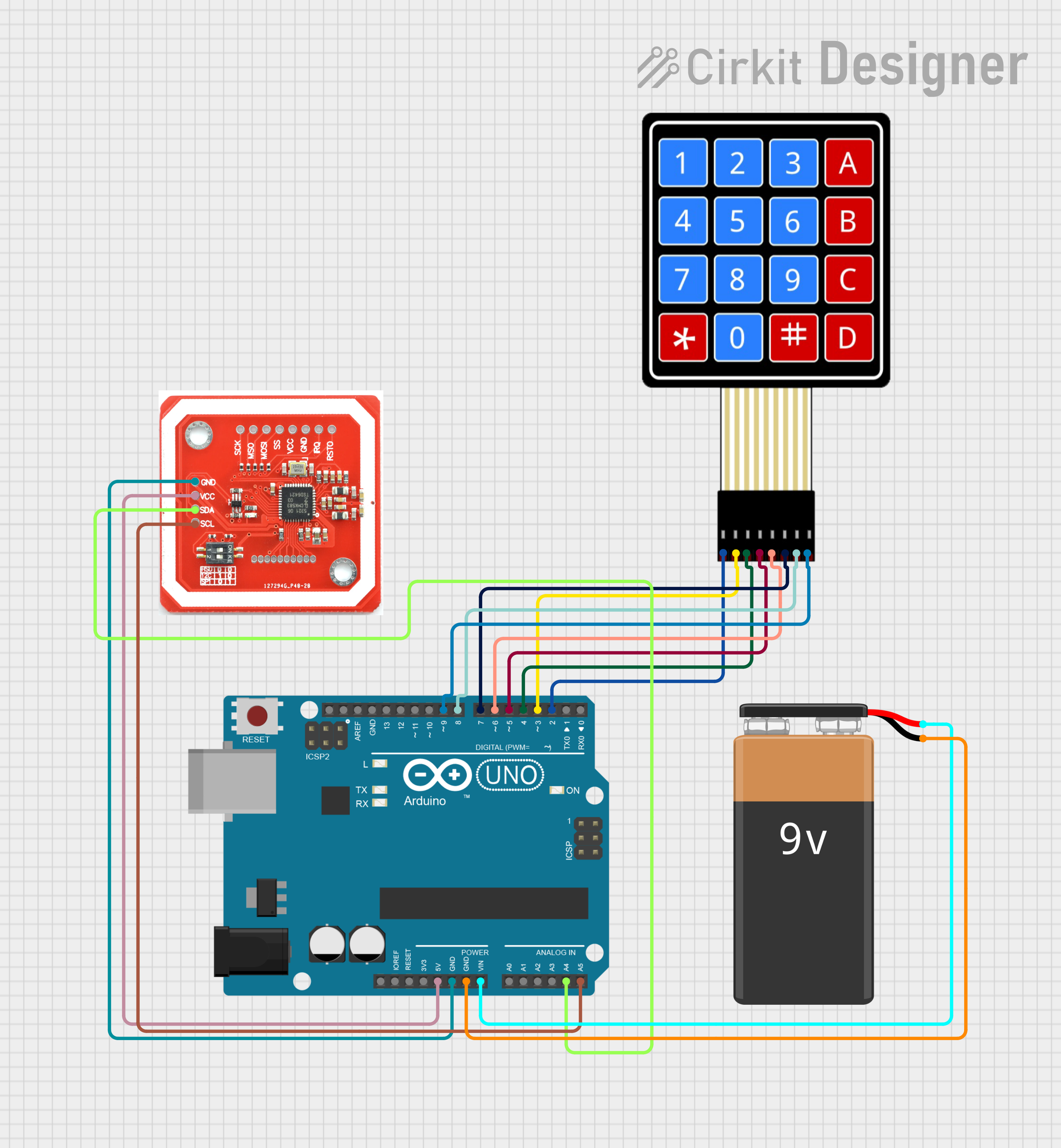
Example: Using the Keypad with an Arduino UNO

Below is an example of interfacing the keypad with an Arduino UNO using the Keypad library.

Circuit Connections

Keypad Pin Arduino Pin
R1 D2
R2 D3
R3 D4
C1 D5
C2 D6
C3 D7

Arduino Code

#include <Keypad.h>

// Define the rows and columns of the keypad
const byte ROWS = 3; // 3 rows
const byte COLS = 4; // 4 columns

// Define the keymap (button layout)
char keys[ROWS][COLS] = {
  {'1', '2', '3', 'A'},
  {'4', '5', '6', 'B'},
  {'7', '8', '9', 'C'},
  {'*', '0', '#', 'D'}
};

// Define the row and column pins
byte rowPins[ROWS] = {2, 3, 4}; // Connect to R1, R2, R3
byte colPins[COLS] = {5, 6, 7, 8}; // Connect to C1, C2, C3, C4

// Create the Keypad object
Keypad keypad = Keypad(makeKeymap(keys), rowPins, colPins, ROWS, COLS);

void setup() {
  Serial.begin(9600); // Initialize serial communication
  Serial.println("Keypad Test Ready");
}

void loop() {
  char key = keypad.getKey(); // Check for key press

  if (key) {
    // Print the key to the Serial Monitor
    Serial.print("Key Pressed: ");
    Serial.println(key);
  }
}

Note: Install the Keypad library in the Arduino IDE via the Library Manager if not already installed.

Troubleshooting and FAQs

Common Issues

  1. No Key Press Detected:

    • Check the wiring between the keypad and the microcontroller.
    • Ensure the correct pins are defined in the code.
    • Verify that pull-up resistors are enabled or connected.
  2. Incorrect Key Presses:

    • Ensure the keymap in the code matches the physical layout of the keypad.
    • Check for loose or damaged connections.
  3. Multiple Keys Detected:

    • This may be caused by electrical noise or poor debouncing.
    • Implement software debouncing in the code.

FAQs

  • Can I use this keypad with a Raspberry Pi?
    Yes, but you will need to use GPIO pins and a library like gpiozero or RPI.GPIO to scan the matrix.

  • What is the maximum cable length for connecting the keypad?
    For reliable operation, keep the cable length under 1 meter to minimize signal degradation.

  • Can I use this keypad with a 4x4 keymap?
    No, this keypad is designed for a 3x4 layout. The 4th column (C4) is unused.

  • How do I clean the keypad?
    Use a soft, dry cloth to clean the surface. Avoid using liquids or abrasive materials.

By following this documentation, you can effectively integrate the 3x4 Phone-Style Matrix Keypad (Adafruit Art.-Nr.: AF1824) into your projects for reliable and efficient user input.