Cirkit Designer Logo
Cirkit Designer
Your all-in-one circuit design IDE
Home / 
Component Documentation

How to Use IRF520 PWM: Examples, Pinouts, and Specs

Image of IRF520 PWM
Cirkit Designer LogoDesign with IRF520 PWM in Cirkit Designer

Introduction

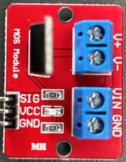
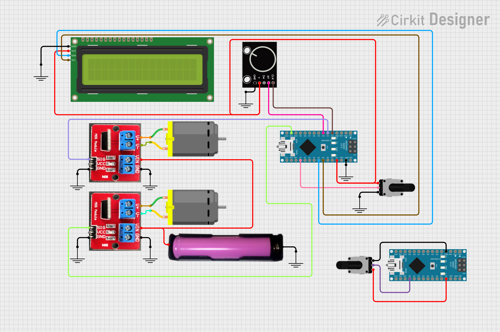
The IRF520 PWM module is a versatile and powerful electronic component designed for controlling high-power loads with digital signals. It is based on the IRF520 power MOSFET and is capable of handling high currents and voltages. This module is commonly used in applications involving Pulse Width Modulation (PWM) to control the power delivered to devices such as motors, LEDs, and heating elements. Its ease of use and robustness make it a popular choice for hobbyists and professionals alike.

Explore Projects Built with IRF520 PWM

Use Cirkit Designer to design, explore, and prototype these projects online. Some projects support real-time simulation. Click "Open Project" to start designing instantly!
Arduino Mega 2560 Controlled 12V LED Strip with Potentiometer and IRF520 PWM
Image of Backlight: A project utilizing IRF520 PWM in a practical application
This circuit uses an Arduino Mega 2560 to control the brightness of a 12V white LED strip via a potentiometer and an IRF520 PWM module. The potentiometer adjusts the input signal to the Arduino, which then modulates the LED strip's brightness through the IRF520 PWM module, powered by a 12V power supply.
Cirkit Designer LogoOpen Project in Cirkit Designer
Arduino UNO-Based Smart Fan Controller with Temperature and Humidity Sensing
Image of 123: A project utilizing IRF520 PWM in a practical application
This circuit uses an Arduino UNO to control a 12V fan and two LEDs (red and blue) based on input from a DHT11 humidity and temperature sensor. The IRF520 PWM module is used to drive the fan, and the LEDs are connected through resistors to the Arduino's digital pins for status indication.
Cirkit Designer LogoOpen Project in Cirkit Designer
Arduino Nano Controlled Multi-Stepper Motor System with Limit Switches and Emergency Stop
Image of CNC : A project utilizing IRF520 PWM in a practical application
This circuit controls multiple stepper motors and a DC motor using an Arduino Nano, TB6600 motor drivers, and an IRF520 PWM module. The Arduino Nano interfaces with limit switches and pushbuttons for user input and safety, while a switching power supply provides the necessary power. The setup is designed for precise motor control applications, likely in an automation or CNC system.
Cirkit Designer LogoOpen Project in Cirkit Designer
Arduino Nano-Based Dual DC Motor Controller with Rotary Encoder and I2C LCD Display
Image of dron: A project utilizing IRF520 PWM in a practical application
This circuit uses two Arduino Nano microcontrollers to control two DC motors via IRF520 PWM modules, with inputs from rotary encoders and potentiometers. The system also includes a 16x2 I2C LCD for display purposes, powered by a 18650 battery holder, and is designed for motor control and user interface applications.
Cirkit Designer LogoOpen Project in Cirkit Designer

Explore Projects Built with IRF520 PWM

Use Cirkit Designer to design, explore, and prototype these projects online. Some projects support real-time simulation. Click "Open Project" to start designing instantly!
Image of Backlight: A project utilizing IRF520 PWM in a practical application
Arduino Mega 2560 Controlled 12V LED Strip with Potentiometer and IRF520 PWM
This circuit uses an Arduino Mega 2560 to control the brightness of a 12V white LED strip via a potentiometer and an IRF520 PWM module. The potentiometer adjusts the input signal to the Arduino, which then modulates the LED strip's brightness through the IRF520 PWM module, powered by a 12V power supply.
Cirkit Designer LogoOpen Project in Cirkit Designer
Image of 123: A project utilizing IRF520 PWM in a practical application
Arduino UNO-Based Smart Fan Controller with Temperature and Humidity Sensing
This circuit uses an Arduino UNO to control a 12V fan and two LEDs (red and blue) based on input from a DHT11 humidity and temperature sensor. The IRF520 PWM module is used to drive the fan, and the LEDs are connected through resistors to the Arduino's digital pins for status indication.
Cirkit Designer LogoOpen Project in Cirkit Designer
Image of CNC : A project utilizing IRF520 PWM in a practical application
Arduino Nano Controlled Multi-Stepper Motor System with Limit Switches and Emergency Stop
This circuit controls multiple stepper motors and a DC motor using an Arduino Nano, TB6600 motor drivers, and an IRF520 PWM module. The Arduino Nano interfaces with limit switches and pushbuttons for user input and safety, while a switching power supply provides the necessary power. The setup is designed for precise motor control applications, likely in an automation or CNC system.
Cirkit Designer LogoOpen Project in Cirkit Designer
Image of dron: A project utilizing IRF520 PWM in a practical application
Arduino Nano-Based Dual DC Motor Controller with Rotary Encoder and I2C LCD Display
This circuit uses two Arduino Nano microcontrollers to control two DC motors via IRF520 PWM modules, with inputs from rotary encoders and potentiometers. The system also includes a 16x2 I2C LCD for display purposes, powered by a 18650 battery holder, and is designed for motor control and user interface applications.
Cirkit Designer LogoOpen Project in Cirkit Designer

Common Applications and Use Cases
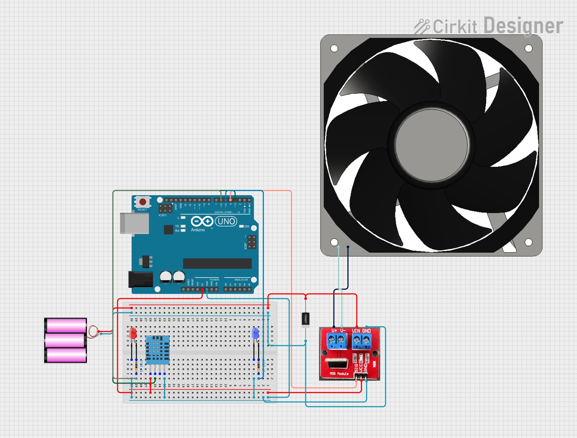
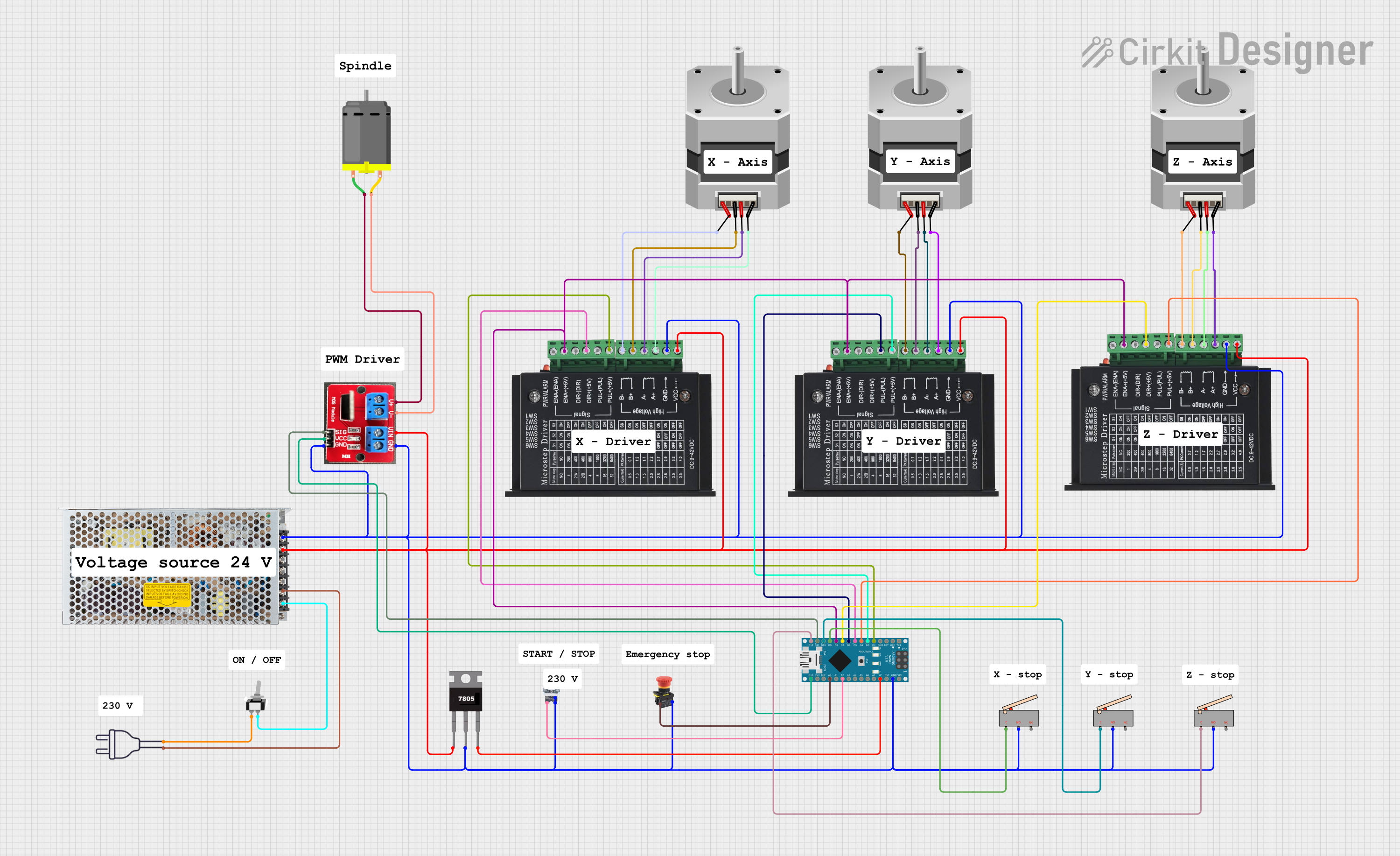
  • Motor speed control
  • LED dimming and RGB lighting
  • Heating elements control
  • Switching high-power loads with microcontrollers

Technical Specifications

Key Technical Details

  • Voltage Rating (VDS): 100V
  • Drain Current (ID): 9.7A
  • Power Dissipation (PD): 60W
  • RDS(on): 0.27Ω at VGS = 10V
  • Gate Threshold Voltage (VGS(th)): 2.0V to 4.0V

Pin Configuration and Descriptions

Pin Number Name Description
1 V+ Power supply input, connects to the positive voltage source
2 GND Ground connection
3 SIG Signal input, accepts PWM signal from a microcontroller
4 V- Power output to the load, connects to the negative side of the load
5 GND Ground for the load

Usage Instructions

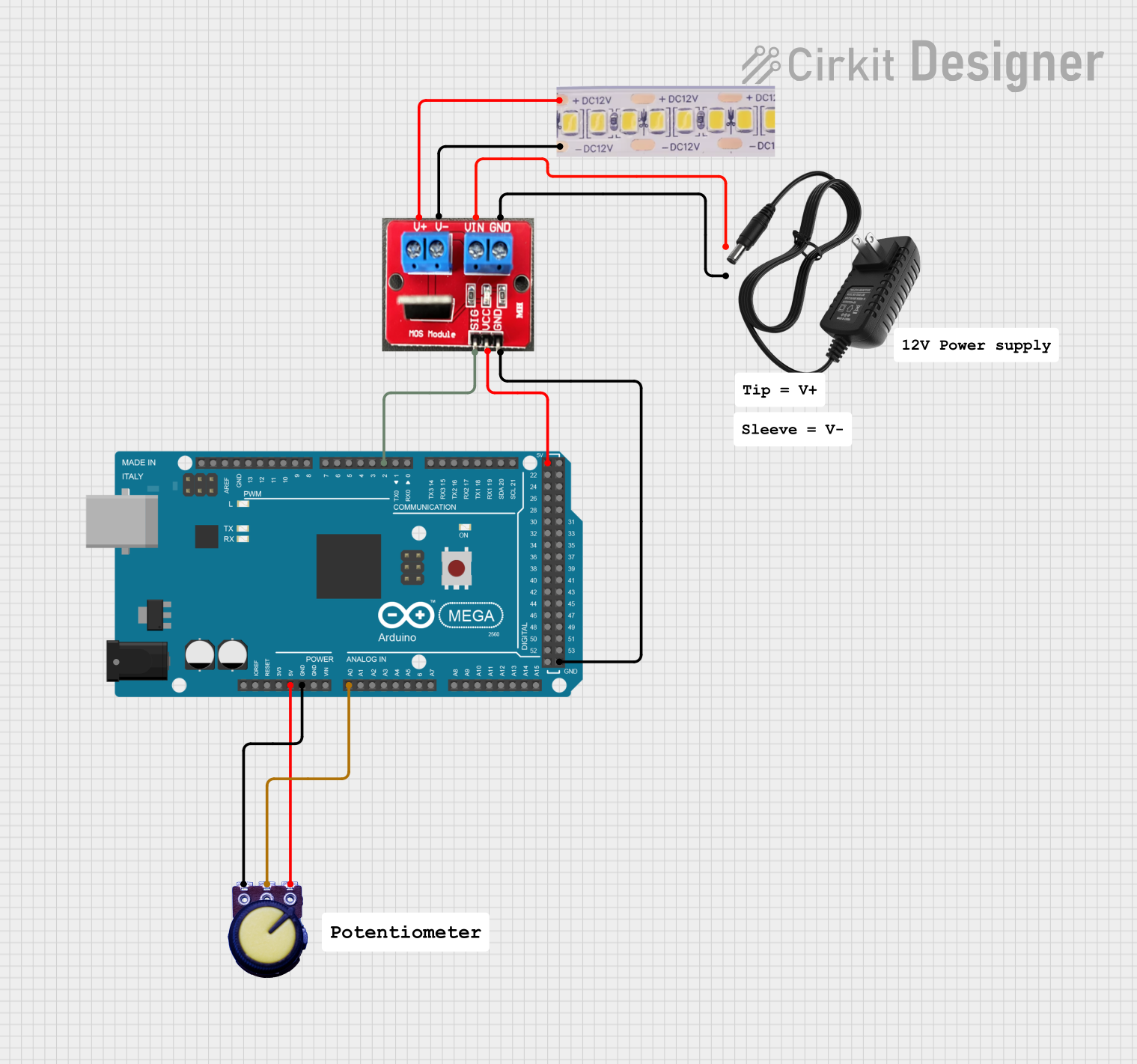
How to Use the Component in a Circuit

  1. Connect the V+ pin to a positive voltage source suitable for your load.
  2. Connect the GND pin to the common ground of your power supply and microcontroller.
  3. Connect the SIG pin to a PWM-capable digital output on your microcontroller.
  4. Connect the load between the V- pin and the positive terminal of your power supply.

Important Considerations and Best Practices

  • Ensure the power supply voltage does not exceed the maximum VDS rating of the module.
  • The total current through the load should not exceed the maximum ID rating.
  • Use a heatsink if the power dissipation is expected to be high during operation.
  • Always provide a proper gate signal; floating gate can lead to unpredictable behavior.
  • Use a flyback diode when controlling inductive loads to prevent voltage spikes.

Example Code for Arduino UNO

// Define the PWM signal pin connected to the IRF520 module
const int pwmPin = 3;

void setup() {
  // Set the PWM pin as an output
  pinMode(pwmPin, OUTPUT);
}

void loop() {
  // Increase the brightness gradually
  for (int dutyCycle = 0; dutyCycle <= 255; dutyCycle++) {
    // Write the PWM signal to the IRF520 module
    analogWrite(pwmPin, dutyCycle);
    delay(10);
  }

  // Decrease the brightness gradually
  for (int dutyCycle = 255; dutyCycle >= 0; dutyCycle--) {
    analogWrite(pwmPin, dutyCycle);
    delay(10);
  }
}

Troubleshooting and FAQs

Common Issues Users Might Face

  • LEDs or motor not responding to PWM signal: Check the connections and ensure the signal pin is configured correctly in the code.
  • Module overheating: Ensure the current through the MOSFET does not exceed the rated ID and that a heatsink is used if necessary.
  • Unexpected behavior when switching inductive loads: Make sure a flyback diode is installed across the load.

Solutions and Tips for Troubleshooting

  • Double-check wiring against the pin configuration table.
  • Use a multimeter to verify the presence of the PWM signal at the SIG pin.
  • If using a microcontroller, ensure the code is uploaded correctly and the correct pin is defined for PWM output.

FAQs

Q: Can I control the IRF520 PWM module with a 3.3V logic level? A: Yes, but the performance may be reduced as the gate threshold voltage is between 2.0V and 4.0V.

Q: What is the maximum frequency for the PWM signal? A: The IRF520 can typically handle PWM frequencies up to several kHz. Check the datasheet for exact figures.

Q: Is it necessary to use a heatsink? A: It depends on the current through the MOSFET and the ambient temperature. If the MOSFET is getting hot to the touch, a heatsink is recommended.

Q: Can I use this module to switch AC loads? A: No, the IRF520 is designed for DC loads only. Switching AC loads requires different types of components such as TRIACs or relays designed for AC operation.