Cirkit Designer
Your all-in-one circuit design IDE
Home /
Component Documentation
How to Use Adafruit SDIO microSD Breakout: Examples, Pinouts, and Specs
Introduction
The Adafruit SDIO microSD Breakout is a versatile and compact breakout board designed for interfacing microSD cards with microcontrollers and other digital devices using the SD Input/Output (SDIO) protocol. This breakout board is particularly useful for applications requiring high-speed data logging, multimedia storage, or extending the storage capabilities of a device.
Explore Projects Built with Adafruit SDIO microSD Breakout
Arduino UNO R4 WiFi Environmental Data Logger with I2C Multiplexing and SD Storage
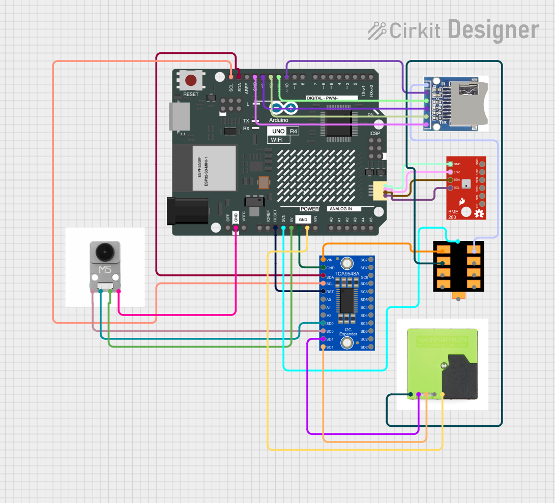
This circuit features an Arduino UNO R4 WiFi as the central microcontroller, interfaced with a BME280 Breakout sensor for environmental data, an SD card module for data logging, and a TCA9548A I2C multiplexer to manage multiple I2C devices. It also includes a U078-V-M12 sensor and an SPS30 particulate matter sensor, both connected through the I2C multiplexer. Power distribution is managed by a dedicated board that receives 3.3V from the Arduino and distributes it to the SD card module and other components.
Arduino Mega 2560-Based Real-Time Clock and Data Logging System with OLED Display
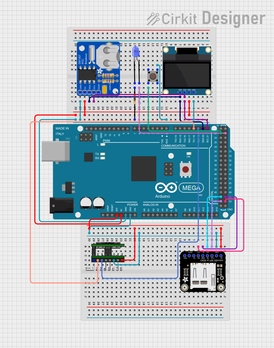
This circuit features an Arduino Mega 2560 microcontroller interfaced with an OLED display, a DS1307 RTC module, a microSD card breakout, a pushbutton, and a blue LED. The Arduino handles data logging to the microSD card, displays information on the OLED, and reads real-time data from the RTC module, while the pushbutton and LED provide user interaction and status indication.
Arduino UNO SD Card Data Logger
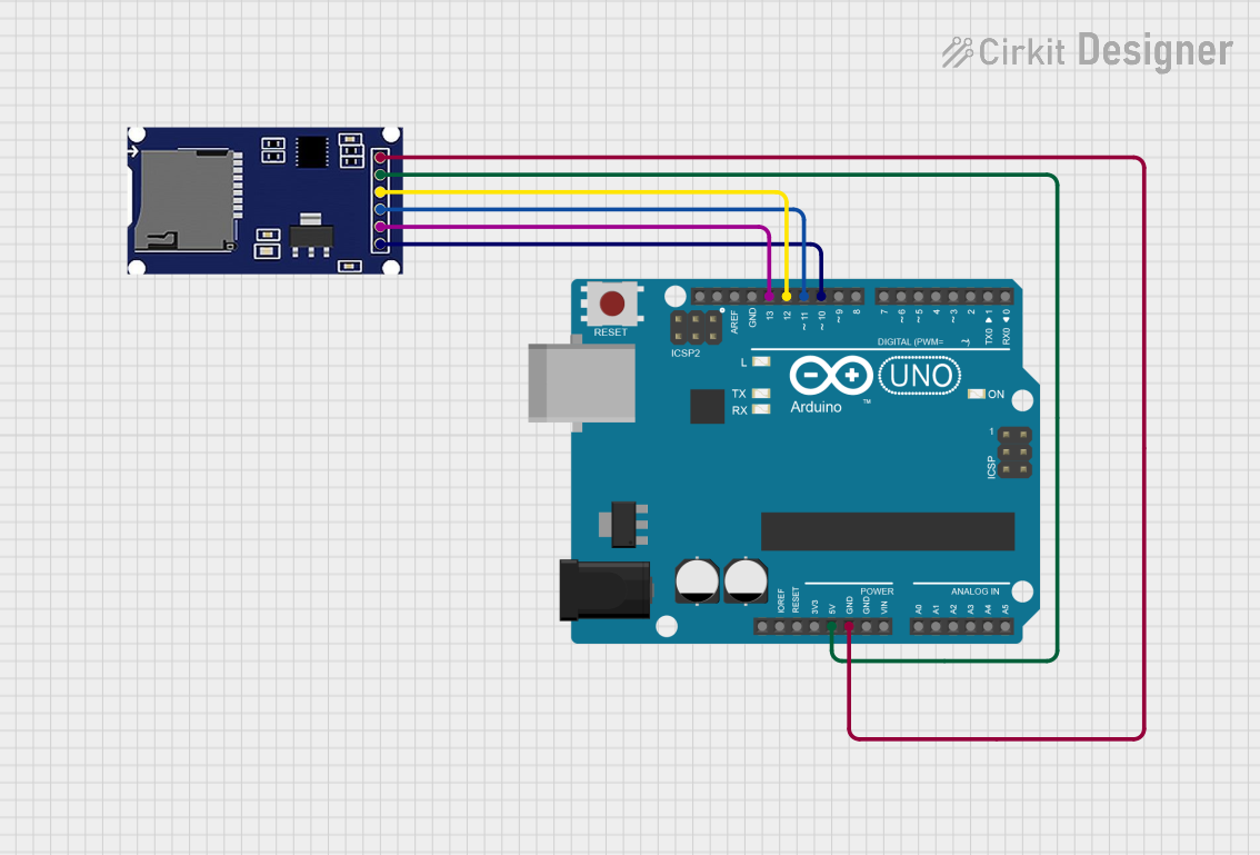
This circuit consists of an Arduino UNO connected to an SD card module. The Arduino provides power and ground to the SD module and interfaces with it using SPI communication through digital pins D10 (CS), D11 (MOSI), D12 (MISO), and D13 (SCK). The setup is intended for reading from or writing to an SD card using the Arduino.
Arduino UNO R4 WiFi Controlled Data Logger with BNO055 Sensor and Micro SD Storage
This circuit features an Arduino UNO R4 WiFi microcontroller connected to a Micro SD Card Module for data storage, a BNO055 sensor for orientation data, and three red LEDs for indication purposes. The LEDs are controlled by digital pins D2, D3, and D4, and can be turned on or off using a single-pole single-throw (SPST) toggle switch connected to their common cathodes and ground. The BNO055 sensor interfaces with the Arduino via I2C communication using the SDA and SCL pins, and the Micro SD Card Module is interfaced using SPI with chip select on pin D10 and data lines on pins D11 (MOSI), D12 (MISO), and D13 (SCK).
Explore Projects Built with Adafruit SDIO microSD Breakout
Arduino UNO R4 WiFi Environmental Data Logger with I2C Multiplexing and SD Storage
This circuit features an Arduino UNO R4 WiFi as the central microcontroller, interfaced with a BME280 Breakout sensor for environmental data, an SD card module for data logging, and a TCA9548A I2C multiplexer to manage multiple I2C devices. It also includes a U078-V-M12 sensor and an SPS30 particulate matter sensor, both connected through the I2C multiplexer. Power distribution is managed by a dedicated board that receives 3.3V from the Arduino and distributes it to the SD card module and other components.
Arduino Mega 2560-Based Real-Time Clock and Data Logging System with OLED Display
This circuit features an Arduino Mega 2560 microcontroller interfaced with an OLED display, a DS1307 RTC module, a microSD card breakout, a pushbutton, and a blue LED. The Arduino handles data logging to the microSD card, displays information on the OLED, and reads real-time data from the RTC module, while the pushbutton and LED provide user interaction and status indication.
Arduino UNO SD Card Data Logger
This circuit consists of an Arduino UNO connected to an SD card module. The Arduino provides power and ground to the SD module and interfaces with it using SPI communication through digital pins D10 (CS), D11 (MOSI), D12 (MISO), and D13 (SCK). The setup is intended for reading from or writing to an SD card using the Arduino.
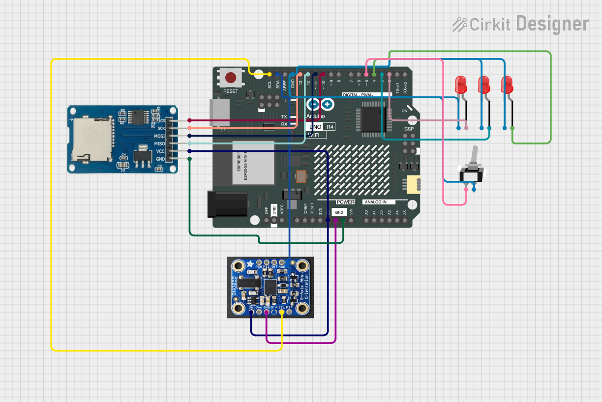
Arduino UNO R4 WiFi Controlled Data Logger with BNO055 Sensor and Micro SD Storage
This circuit features an Arduino UNO R4 WiFi microcontroller connected to a Micro SD Card Module for data storage, a BNO055 sensor for orientation data, and three red LEDs for indication purposes. The LEDs are controlled by digital pins D2, D3, and D4, and can be turned on or off using a single-pole single-throw (SPST) toggle switch connected to their common cathodes and ground. The BNO055 sensor interfaces with the Arduino via I2C communication using the SDA and SCL pins, and the Micro SD Card Module is interfaced using SPI with chip select on pin D10 and data lines on pins D11 (MOSI), D12 (MISO), and D13 (SCK).
Common Applications and Use Cases
- Data logging with high write/read speeds
- Storing configuration files for embedded systems
- Multimedia storage for audio and video playback
- IoT devices requiring additional storage
- Portable storage solutions for microcontroller projects
Technical Specifications
Key Technical Details
- Interface: SDIO (3.0 compatible)
- Voltage: 3.3V input
- Current: Depends on microSD card and usage
- Dimensions: 25mm x 28mm x 2.5mm
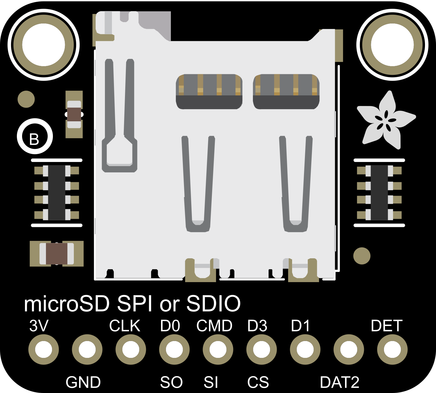
Pin Configuration and Descriptions
| Pin Number | Name | Description |
|---|---|---|
| 1 | GND | Ground connection |
| 2 | 3V3 | 3.3V power supply input |
| 3 | CLK | Clock signal for SDIO communication |
| 4 | CMD | Command line for SDIO communication |
| 5 | DAT0 | Data line 0 for SDIO communication |
| 6 | DAT1 | Data line 1 for SDIO communication (optional) |
| 7 | DAT2 | Data line 2 for SDIO communication (optional) |
| 8 | DAT3 | Data line 3 for SDIO communication (optional) |
| 9 | CD | Card Detect (optional use) |
Usage Instructions
How to Use the Component in a Circuit
- Power Supply: Connect the 3V3 pin to a 3.3V power source and the GND pin to the ground.
- SDIO Interface: Connect the CLK, CMD, and DAT0 (mandatory) pins to the corresponding SDIO pins on your microcontroller. DAT1, DAT2, and DAT3 are optional for 4-bit data transfer mode.
- Card Detect (CD): Optionally, connect the CD pin to a GPIO pin on your microcontroller to detect the presence of a microSD card.
Important Considerations and Best Practices
- Ensure that the power supply is stable and clean to prevent data corruption.
- Use a level shifter if your microcontroller operates at a voltage higher than 3.3V.
- Format the microSD card to the appropriate file system that your microcontroller supports (e.g., FAT32).
- For high-speed data transfer, use a microSD card with a fast read/write speed.
- Always safely eject the microSD card from your computer before removing it to prevent data loss.
Troubleshooting and FAQs
Common Issues Users Might Face
- MicroSD card not recognized: Check the connections and ensure that the card is inserted correctly. Also, verify that the microSD card is formatted properly.
- Data corruption: Ensure a stable power supply and avoid removing the microSD card while writing/reading data.
- Slow data transfer: Use a class 10 or higher microSD card for better speed.
Solutions and Tips for Troubleshooting
- If the microSD card is not detected, try using another card to rule out a defective card.
- For data corruption issues, reformat the microSD card and check the power supply for fluctuations.
- For slow data transfer, ensure that the SDIO interface is configured correctly for the maximum supported bus width.
Example Code for Arduino UNO
#include <SPI.h>
#include <SD.h>

// Pin configuration for the Adafruit SDIO microSD Breakout
const int chipSelect = 10; // Chip select pin for the SD card

void setup() {
  Serial.begin(9600);
  while (!Serial) {
    ; // Wait for serial port to connect.
  }

  Serial.print("Initializing SD card...");

  // Note: The following line is for compatibility with default SPI pins
  if (!SD.begin(chipSelect)) {
    Serial.println("initialization failed!");
    return;
  }
  Serial.println("initialization done.");

  // Rest of the setup code
}

void loop() {
  // Main code to read/write from/to the SD card
}
Note: This example assumes that the SD library is compatible with the Adafruit SDIO microSD Breakout and that the breakout board is wired to the SPI pins of the Arduino UNO. The chip select pin can be connected to any available digital pin, but pin 10 is commonly used for this purpose.