How to Use LM5007: Examples, Pinouts, and Specs
Introduction
The LM5007 is a high-voltage step-down switching regulator designed to provide efficient power conversion from a higher input voltage to a lower output voltage. It is part of the LM5000 series of regulators from Texas Instruments and is suitable for a wide range of applications, including industrial power supplies, automotive systems, and distributed power systems. The LM5007 is known for its high efficiency, thermal performance, and flexibility, making it a popular choice for designers who require a stable and precise power supply.
Explore Projects Built with LM5007

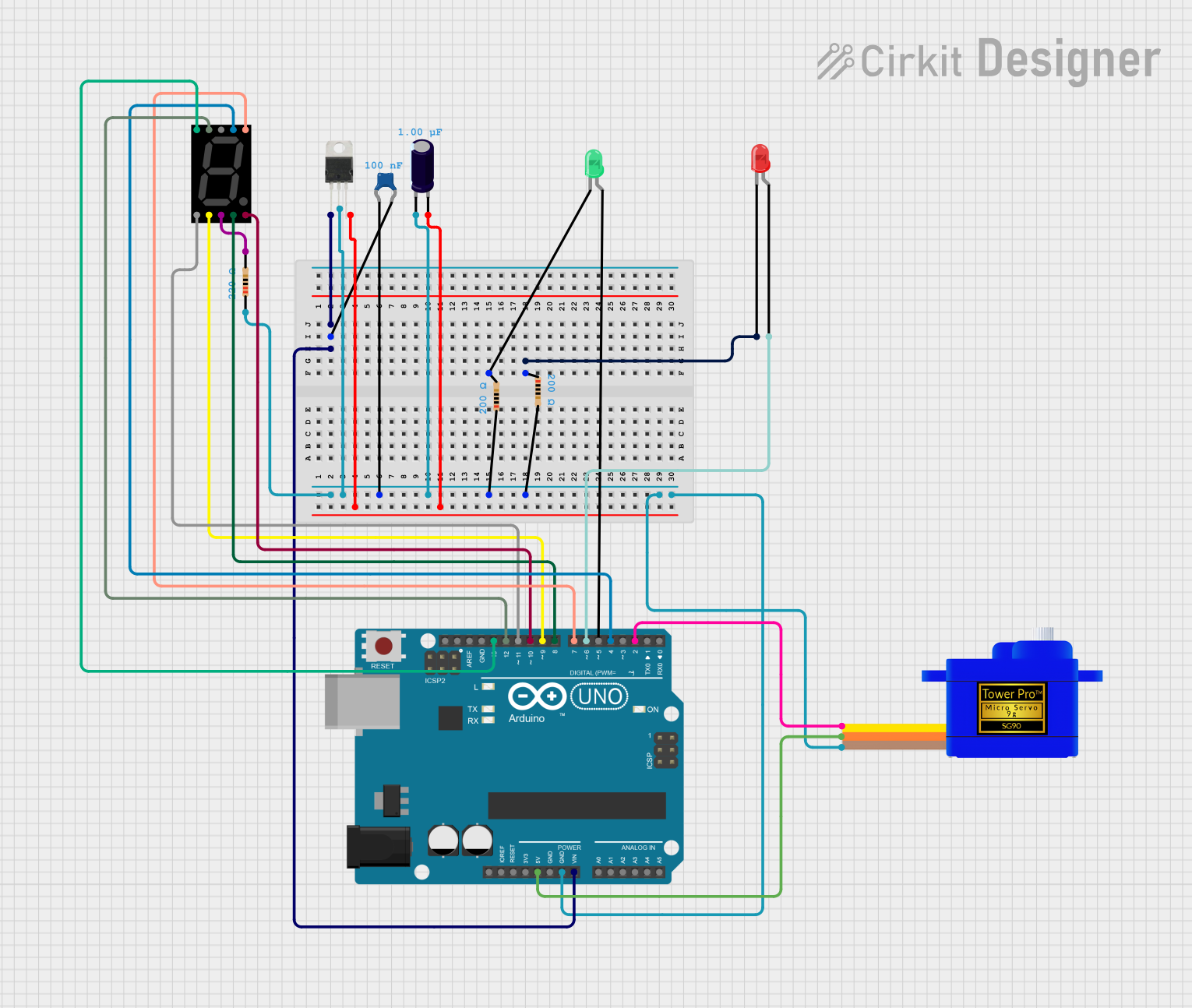
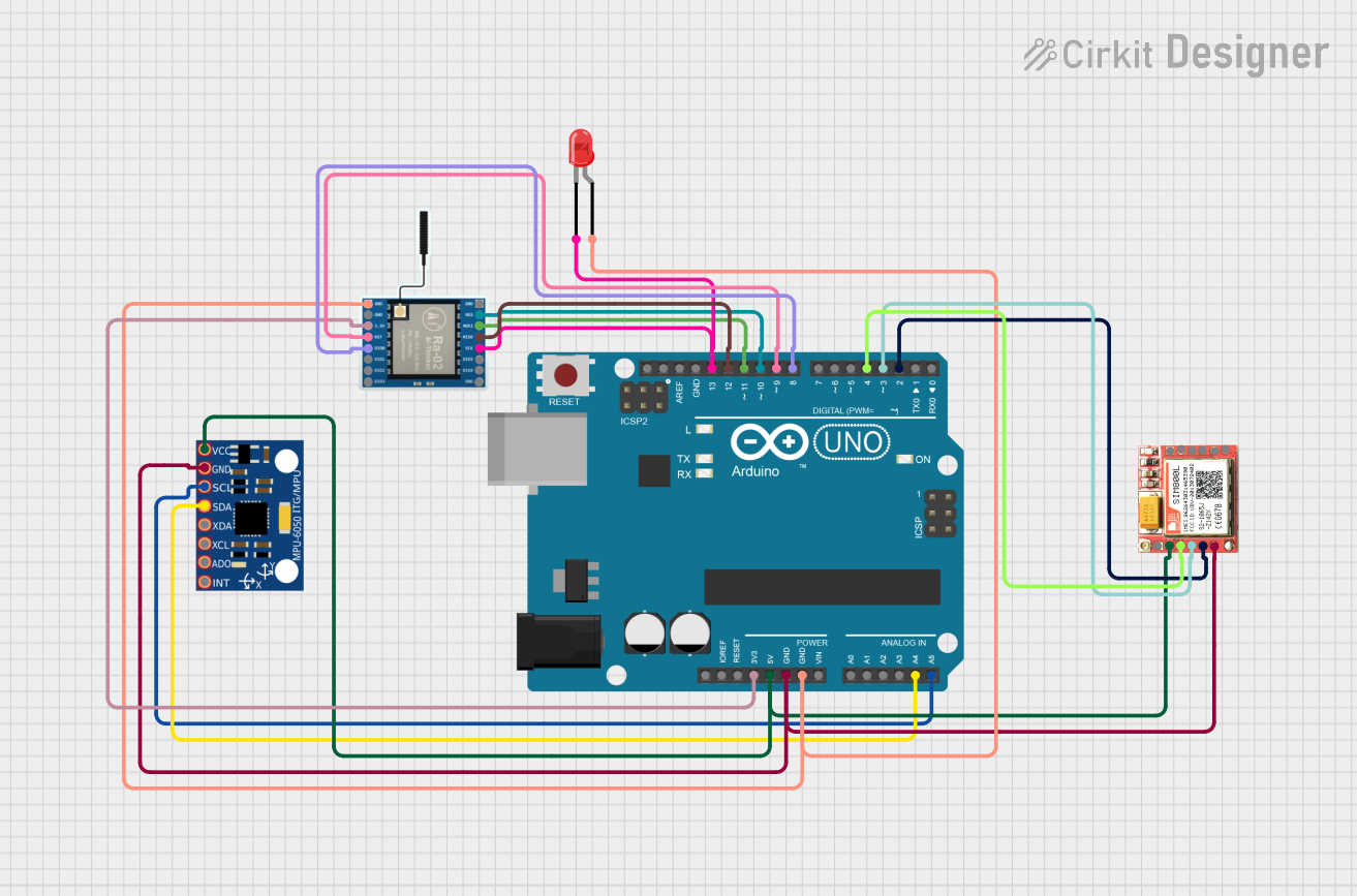

Explore Projects Built with LM5007
Common Applications and Use Cases
- Industrial power systems
- Automotive electronics
- Telecommunications equipment
- Distributed power supplies
- Battery-operated devices
Technical Specifications
Key Technical Details
- Input Voltage Range: 6V to 75V
- Output Voltage Range: 1.225V to 50V
- Output Current: Up to 0.5A
- Switching Frequency: 50kHz to 500kHz (adjustable)
- Operating Temperature Range: -40°C to 125°C
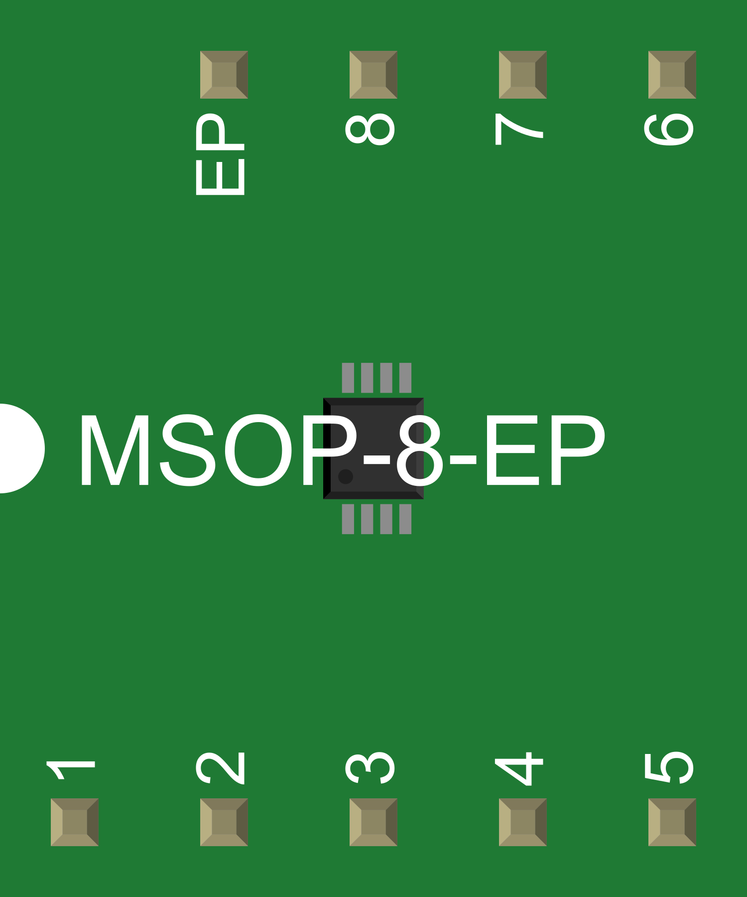
- Package: 8-pin WSON and 8-pin SOIC
Pin Configuration and Descriptions
| Pin Number | Name | Description |
|---|---|---|
| 1 | VIN | Input voltage supply pin. Connect to the high-voltage source. |
| 2 | GND | Ground reference for the regulator. |
| 3 | ON/OFF | Enable pin for the regulator. Drive high to turn on, low to turn off. |
| 4 | SS/TR | Soft-start and tracking pin. Connect a capacitor to set the soft-start time. |
| 5 | FB | Feedback pin. Connect to the output voltage divider to set the output voltage. |
| 6 | COMP | Compensation pin. Connect a network of resistors and capacitors for loop stability. |
| 7 | RT/SYNC | Resistor timing and synchronization pin. Set the switching frequency with a resistor or synchronize to an external clock. |
| 8 | OUT | Switched output voltage. Connect to the inductor and output filter. |
Usage Instructions
How to Use the Component in a Circuit
- Input Supply Connection: Connect a suitable input voltage (6V to 75V) to the VIN pin and reference the GND pin to the system ground.
- Output Voltage Setting: Use a voltage divider from the output to the FB pin to set the desired output voltage. The feedback threshold is typically 1.225V.
- Soft-Start: Connect a capacitor to the SS/TR pin to control the soft-start period, which limits inrush current during startup.
- Frequency Setting: Place a resistor between the RT/SYNC pin and GND to set the internal oscillator frequency, or connect an external clock signal for synchronization.
- Compensation Network: Design a compensation network connected to the COMP pin to ensure stability of the voltage regulation loop.
- Enable Control: The ON/OFF pin can be driven by an external logic signal to enable or disable the regulator.
Important Considerations and Best Practices
- Ensure that the input voltage does not exceed the maximum rating of 75V.
- Proper thermal management is crucial. Use adequate heat sinking if the regulator is expected to dissipate significant power.
- Place decoupling capacitors close to the VIN and OUT pins to minimize voltage spikes and noise.
- Keep the feedback and compensation networks as close to the IC as possible to avoid noise pickup.
- Use a Schottky diode with a suitable voltage and current rating for the catch diode.
Troubleshooting and FAQs
Common Issues Users Might Face
- Output Voltage Instability: This can be caused by improper compensation network design or inadequate feedback trace routing.
- Excessive Heat Generation: This may occur if the power dissipation is too high for the chosen package or if the ambient temperature is too high.
Solutions and Tips for Troubleshooting
- Verify the compensation network and adjust components as necessary for stability.
- Ensure that the input and output capacitors are of adequate value and low ESR type.
- Check the thermal design and improve heat sinking or airflow if necessary.
- Confirm that the ON/OFF pin is being driven correctly for proper enable/disable function.
FAQs
Q: Can the LM5007 be synchronized to an external clock? A: Yes, the LM5007 can be synchronized to an external clock by applying the clock signal to the RT/SYNC pin.
Q: What is the purpose of the soft-start feature? A: The soft-start feature controls the inrush current during startup, providing a gradual increase in output voltage to prevent overshoot and stress on the components.
Q: How do I adjust the switching frequency of the LM5007? A: The switching frequency can be adjusted by changing the resistor value connected to the RT/SYNC pin or by synchronizing to an external clock.
Q: Is there any protection against overcurrent or overheating? A: The LM5007 includes overcurrent protection and thermal shutdown to protect the device under extreme conditions.
For more detailed information, refer to the LM5007 datasheet provided by Texas Instruments.
(Note: This documentation is a general guide and does not replace the official datasheet. Always consult the datasheet and application notes provided by the manufacturer for the most accurate and comprehensive information.)