How to Use Charging Module: Examples, Pinouts, and Specs
Introduction
A Charging Module is a device designed to manage the charging process of batteries, ensuring they are charged safely and efficiently. It regulates the voltage and current supplied to the battery, preventing overcharging, overheating, or damage to the battery. Charging modules are commonly used in portable electronics, power banks, solar charging systems, and DIY electronics projects.
Explore Projects Built with Charging Module


Explore Projects Built with Charging Module
Common Applications and Use Cases
- Charging lithium-ion (Li-ion) and lithium-polymer (LiPo) batteries
- Power management in portable devices
- Solar-powered battery charging systems
- DIY electronics projects requiring rechargeable power sources
- Battery backup systems
Technical Specifications
Below are the general technical specifications for a typical charging module, such as the TP4056 module, which is widely used for charging single-cell lithium-ion batteries.
Key Technical Details
- Input Voltage: 4.5V to 5.5V (typically powered via USB or DC input)
- Charging Voltage: 4.2V (fixed for single-cell Li-ion/LiPo batteries)
- Charging Current: Adjustable, up to 1A (default: 1A)
- Battery Type: Single-cell lithium-ion or lithium-polymer
- Protection Features: Overcharge, over-discharge, and short-circuit protection
- LED Indicators:
- Red LED: Charging in progress
- Blue LED: Charging complete
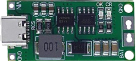
Pin Configuration and Descriptions
The charging module typically has the following pins and connectors:
| Pin/Connector | Description |
|---|---|
| IN+ | Positive input terminal for power supply (e.g., USB 5V or DC input) |
| IN- | Negative input terminal for power supply (ground) |
| BAT+ | Positive terminal for connecting the battery |
| BAT- | Negative terminal for connecting the battery (ground) |
| OUT+ | Positive output terminal for powering the load (optional, connected to BAT+) |
| OUT- | Negative output terminal for powering the load (optional, connected to BAT-) |
Usage Instructions
How to Use the Charging Module in a Circuit
Connect the Power Supply:
- Connect a 5V power source (e.g., USB or DC adapter) to the
IN+andIN-pins. - Ensure the input voltage does not exceed the module's maximum rating (5.5V).
- Connect a 5V power source (e.g., USB or DC adapter) to the
Connect the Battery:
- Attach the positive terminal of the battery to the
BAT+pin. - Attach the negative terminal of the battery to the
BAT-pin. - Ensure the battery is a single-cell lithium-ion or lithium-polymer type.
- Attach the positive terminal of the battery to the
Optional Load Connection:
- If you want to power a load while charging the battery, connect the load to the
OUT+andOUT-pins.
- If you want to power a load while charging the battery, connect the load to the
Monitor the LEDs:
- The red LED indicates the battery is charging.
- The blue LED indicates the battery is fully charged.
Important Considerations and Best Practices
- Battery Compatibility: Only use the module with single-cell lithium-ion or lithium-polymer batteries.
- Heat Management: The module may heat up during operation. Ensure proper ventilation or add a heatsink if necessary.
- Current Adjustment: If the default charging current (1A) is too high for your battery, adjust the current by replacing the onboard resistor (refer to the module's datasheet for details).
- Polarity: Double-check the polarity of all connections to avoid damaging the module or the battery.
- Arduino Integration: The module can be used in Arduino projects to charge batteries for powering the microcontroller.
Example Arduino Code for Monitoring Battery Voltage
You can use an Arduino UNO to monitor the battery voltage connected to the charging module. Below is an example code:
// Define the analog pin connected to the battery's positive terminal
const int batteryPin = A0;

void setup() {
  Serial.begin(9600); // Initialize serial communication at 9600 baud
}

void loop() {
  int sensorValue = analogRead(batteryPin); // Read the analog value
  float voltage = sensorValue * (5.0 / 1023.0); // Convert to voltage (assuming 5V reference)

  // Print the battery voltage to the Serial Monitor
  Serial.print("Battery Voltage: ");
  Serial.print(voltage);
  Serial.println(" V");

  delay(1000); // Wait for 1 second before the next reading
}
Note: Use a voltage divider circuit if the battery voltage exceeds the Arduino's input voltage range (5V for most boards).
Troubleshooting and FAQs
Common Issues and Solutions
Module Overheating:
- Cause: High charging current or insufficient ventilation.
- Solution: Reduce the charging current by replacing the onboard resistor or improve ventilation.
Battery Not Charging:
- Cause: Incorrect wiring or damaged battery.
- Solution: Verify all connections and ensure the battery is functional.
LEDs Not Lighting Up:
- Cause: No power supply or faulty module.
- Solution: Check the input voltage and ensure the module is not damaged.
Load Not Powering On:
- Cause: Insufficient battery charge or incorrect load connection.
- Solution: Ensure the battery is charged and the load is connected to the correct pins.
FAQs
Can I use this module to charge multiple batteries in series?
- No, this module is designed for single-cell batteries only. Charging multiple batteries in series requires a specialized charger.
What happens if I leave the battery connected after it is fully charged?
- The module includes overcharge protection, so it will stop charging the battery once it is full.
Can I use a power bank as the input power source?
- Yes, a power bank can be used as long as it provides a stable 5V output.
How do I adjust the charging current?
- Replace the onboard resistor with a different value as specified in the module's datasheet to adjust the charging current.
By following this documentation, you can safely and effectively use a charging module in your projects.