How to Use STEP-UP 2A MT3608 DC-DC USB-C: Examples, Pinouts, and Specs
Introduction
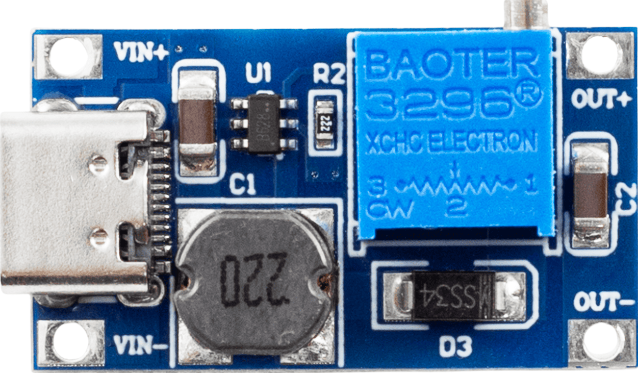
The STEP-UP 2A MT3608 DC-DC USB-C is a compact and efficient boost converter module designed to step up a lower input voltage to a higher output voltage. It is capable of delivering a maximum output current of 2A, making it suitable for a wide range of applications. The module features a USB-C interface for convenient connectivity, allowing it to be easily integrated into modern systems. This component is commonly used in battery-powered devices, portable electronics, and DIY projects where voltage boosting is required.
Explore Projects Built with STEP-UP 2A MT3608 DC-DC USB-C


Explore Projects Built with STEP-UP 2A MT3608 DC-DC USB-C
Common Applications
- Powering devices that require a higher voltage than the available power source.
- Battery-powered systems, such as lithium-ion or AA battery packs.
- DIY electronics projects and prototyping.
- Portable USB-powered devices.
- LED lighting systems requiring higher voltage.
Technical Specifications
Key Specifications
| Parameter | Value |
|---|---|
| Input Voltage Range | 2V to 24V |
| Output Voltage Range | 5V to 28V (adjustable) |
| Maximum Output Current | 2A |
| Efficiency | Up to 93% |
| USB-C Input Port | Yes |
| Dimensions | 36mm x 17mm x 6mm |
| Weight | ~5g |
Pin Configuration and Descriptions
| Pin/Port Name | Type | Description |
|---|---|---|
| USB-C Port | Input | Connects to a USB-C power source for input voltage. |
| VIN+ | Input | Positive input voltage terminal (alternative to USB-C input). |
| VIN- | Input | Negative input voltage terminal (GND). |
| VOUT+ | Output | Positive output voltage terminal. |
| VOUT- | Output | Negative output voltage terminal (GND). |
| Potentiometer | Adjustment | Used to adjust the output voltage. Rotate clockwise to increase voltage. |
Usage Instructions
How to Use the STEP-UP 2A MT3608 in a Circuit
Connect the Input Voltage:
- Use the USB-C port to supply input voltage from a USB power source.
- Alternatively, connect a DC power source to the
VIN+andVIN-terminals. - Ensure the input voltage is within the range of 2V to 24V.
Connect the Output Load:
- Attach the device or circuit requiring boosted voltage to the
VOUT+andVOUT-terminals. - Ensure the load does not exceed the maximum output current of 2A.
- Attach the device or circuit requiring boosted voltage to the
Adjust the Output Voltage:
- Use the onboard potentiometer to set the desired output voltage.
- Rotate the potentiometer clockwise to increase the output voltage and counterclockwise to decrease it.
- Use a multimeter to measure the output voltage while adjusting.
Power On:
- Once all connections are secure, power on the input source.
- Verify the output voltage and ensure it matches the requirements of your load.
Important Considerations
- Heat Dissipation: The module may heat up under high current loads. Ensure proper ventilation or add a heatsink if necessary.
- Input Voltage Limit: Do not exceed the maximum input voltage of 24V to avoid damaging the module.
- Output Voltage Adjustment: Always adjust the output voltage without a load connected to prevent overvoltage damage to your device.
- Polarity: Double-check the polarity of all connections to avoid short circuits or damage.
Example: Using with an Arduino UNO
The STEP-UP 2A MT3608 can be used to power an Arduino UNO from a lower voltage source, such as a 3.7V lithium-ion battery. Below is an example setup:
- Connect the battery to the
VIN+andVIN-terminals of the module. - Adjust the output voltage to 5V using the potentiometer.
- Connect the
VOUT+andVOUT-terminals to the Arduino's5VandGNDpins, respectively.
Sample Arduino Code
// Example: Blink an LED using Arduino UNO powered by the MT3608 module
// Ensure the MT3608 output is set to 5V before connecting to the Arduino.

int ledPin = 13; // Pin connected to the onboard LED

void setup() {
  pinMode(ledPin, OUTPUT); // Set the LED pin as an output
}

void loop() {
  digitalWrite(ledPin, HIGH); // Turn the LED on
  delay(1000);                // Wait for 1 second
  digitalWrite(ledPin, LOW);  // Turn the LED off
  delay(1000);                // Wait for 1 second
}
Troubleshooting and FAQs
Common Issues and Solutions
| Issue | Possible Cause | Solution |
|---|---|---|
| No output voltage | Input voltage not connected or too low | Verify input voltage is within the 2V to 24V range. |
| Output voltage not adjustable | Potentiometer not functioning properly | Check the potentiometer and ensure it is not damaged. |
| Module overheating | Excessive current draw or poor airflow | Reduce the load or add a heatsink for better heat dissipation. |
| Output voltage too high or unstable | Incorrect adjustment or load issue | Re-adjust the potentiometer and ensure the load is within specifications. |
FAQs
Can I use the USB-C port and VIN terminals simultaneously?
- No, use either the USB-C port or the VIN terminals, but not both at the same time.
What happens if I exceed the 2A current limit?
- The module may overheat or shut down. Prolonged overcurrent conditions can damage the module.
Can I use this module to charge a battery?
- While possible, it is not recommended unless you have additional circuitry to regulate the charging process.
How do I know the output voltage is correct?
- Use a multimeter to measure the output voltage before connecting your load.
By following these guidelines and best practices, you can effectively use the STEP-UP 2A MT3608 DC-DC USB-C module in your projects.