How to Use Relay : Examples, Pinouts, and Specs
Introduction
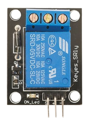
The SRD-05VDC-SL-C is an electromechanical relay manufactured by Ningbo Songle Relay. It is designed to control high-power devices using low-power signals, making it an essential component in automation, home appliances, and embedded systems. The relay operates by energizing an electromagnetic coil, which mechanically switches its contacts to open or close a circuit.
Explore Projects Built with Relay


Explore Projects Built with Relay
Common Applications
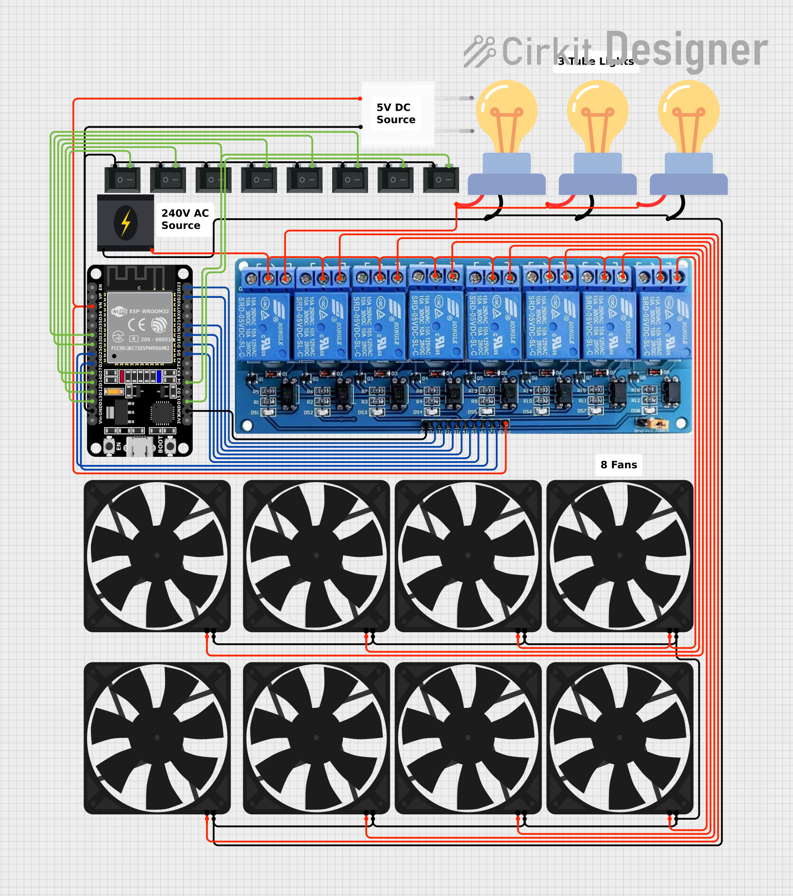
- Home automation systems (e.g., controlling lights, fans, or appliances)
- Industrial control systems
- Motor control circuits
- Microcontroller-based projects (e.g., Arduino, Raspberry Pi)
- Safety and protection circuits
Technical Specifications
Key Technical Details
| Parameter | Value |
|---|---|
| Manufacturer | Ningbo Songle Relay |
| Part Number | SRD-05VDC-SL-C |
| Coil Voltage | 5 V DC |
| Operating Voltage Range | 3.75 V DC to 5.25 V DC |
| Coil Resistance | 70 Ω ±10% |
| Contact Type | SPDT (Single Pole Double Throw) |
| Contact Rating | 10 A at 250 V AC / 10 A at 30 V DC |
| Switching Voltage (Max) | 250 V AC / 30 V DC |
| Switching Current (Max) | 10 A |
| Insulation Resistance | ≥100 MΩ (at 500 V DC) |
| Dielectric Strength | 500 V AC (coil to contact) |
| Dimensions | 19.0 mm x 15.5 mm x 15.0 mm |
| Weight | ~10 g |
Pin Configuration and Descriptions
The SRD-05VDC-SL-C relay has five pins, as described below:
| Pin Number | Name | Description |
|---|---|---|
| 1 | Coil (+) | Positive terminal of the electromagnetic coil |
| 2 | Coil (-) | Negative terminal of the electromagnetic coil |
| 3 | Common (COM) | Common terminal for the relay contacts |
| 4 | Normally Open (NO) | Open circuit when the relay is de-energized; closes when energized |
| 5 | Normally Closed (NC) | Closed circuit when the relay is de-energized; opens when energized |
Usage Instructions
How to Use the Relay in a Circuit
- Power the Coil: Connect the coil pins (1 and 2) to a 5 V DC power source. Use a transistor or MOSFET to control the coil with a microcontroller, as the relay requires more current than most microcontroller GPIO pins can supply.
- Connect the Load:
- Connect the load to the Common (COM) pin (Pin 3).
- Use the Normally Open (NO) pin (Pin 4) if you want the load to be powered only when the relay is energized.
- Use the Normally Closed (NC) pin (Pin 5) if you want the load to be powered when the relay is not energized.
- Add a Flyback Diode: Place a flyback diode (e.g., 1N4007) across the coil terminals to protect the driving circuit from voltage spikes caused by the relay's inductive load.
Example Circuit with Arduino UNO
Below is an example of how to control the SRD-05VDC-SL-C relay using an Arduino UNO:
// Define the relay pin
const int relayPin = 7; // Connect relay control pin to Arduino digital pin 7

void setup() {
  pinMode(relayPin, OUTPUT); // Set relay pin as output
  digitalWrite(relayPin, LOW); // Ensure relay is off at startup
}

void loop() {
  digitalWrite(relayPin, HIGH); // Turn relay on
  delay(1000); // Keep relay on for 1 second
  digitalWrite(relayPin, LOW); // Turn relay off
  delay(1000); // Keep relay off for 1 second
}
Important Considerations
- Driving the Relay: Use a transistor (e.g., 2N2222) or a relay driver IC (e.g., ULN2003) to control the relay from a microcontroller.
- Power Supply: Ensure the power supply can provide sufficient current for the relay coil (approximately 70 mA).
- Isolation: For safety, consider using an optocoupler to isolate the control circuit from the high-power load.
- Contact Ratings: Do not exceed the relay's maximum contact ratings (10 A at 250 V AC or 30 V DC).
Troubleshooting and FAQs
Common Issues
Relay Not Switching:
- Check if the coil voltage is within the operating range (3.75 V to 5.25 V DC).
- Verify that the driving circuit (e.g., transistor or relay driver IC) is functioning correctly.
- Ensure the power supply can provide sufficient current for the relay coil.
Load Not Turning On/Off:
- Confirm that the load is connected to the correct relay pins (COM, NO, or NC).
- Check for loose or incorrect wiring.
- Verify that the load does not exceed the relay's contact ratings.
Microcontroller Resetting:
- Add a flyback diode across the relay coil to suppress voltage spikes.
- Ensure the power supply for the microcontroller is stable and not affected by the relay's operation.
FAQs
Q: Can I use the SRD-05VDC-SL-C relay with a 3.3 V microcontroller?
A: Yes, but you will need a transistor or relay driver IC to step up the control signal to 5 V for the relay coil.
Q: What is the purpose of the flyback diode?
A: The flyback diode protects the driving circuit from voltage spikes generated when the relay coil is de-energized.
Q: Can this relay switch both AC and DC loads?
A: Yes, the SRD-05VDC-SL-C can switch AC loads up to 250 V and DC loads up to 30 V, provided the current does not exceed 10 A.
Q: How do I know if the relay is energized?
A: Many relay modules include an LED indicator that lights up when the relay is energized. If using a bare relay, you can measure the voltage across the coil terminals.