How to Use CDI module: Examples, Pinouts, and Specs
Introduction
The Capacitor Discharge Ignition (CDI) module, manufactured by Adafruit Industries (Part ID: 4546), is an advanced electronic device designed to control ignition timing in internal combustion engines. By storing energy in a capacitor and discharging it to the ignition coil, the CDI module generates a high-voltage spark that ensures efficient combustion of the fuel-air mixture. This results in improved engine performance, fuel efficiency, and reduced emissions.
Explore Projects Built with CDI module
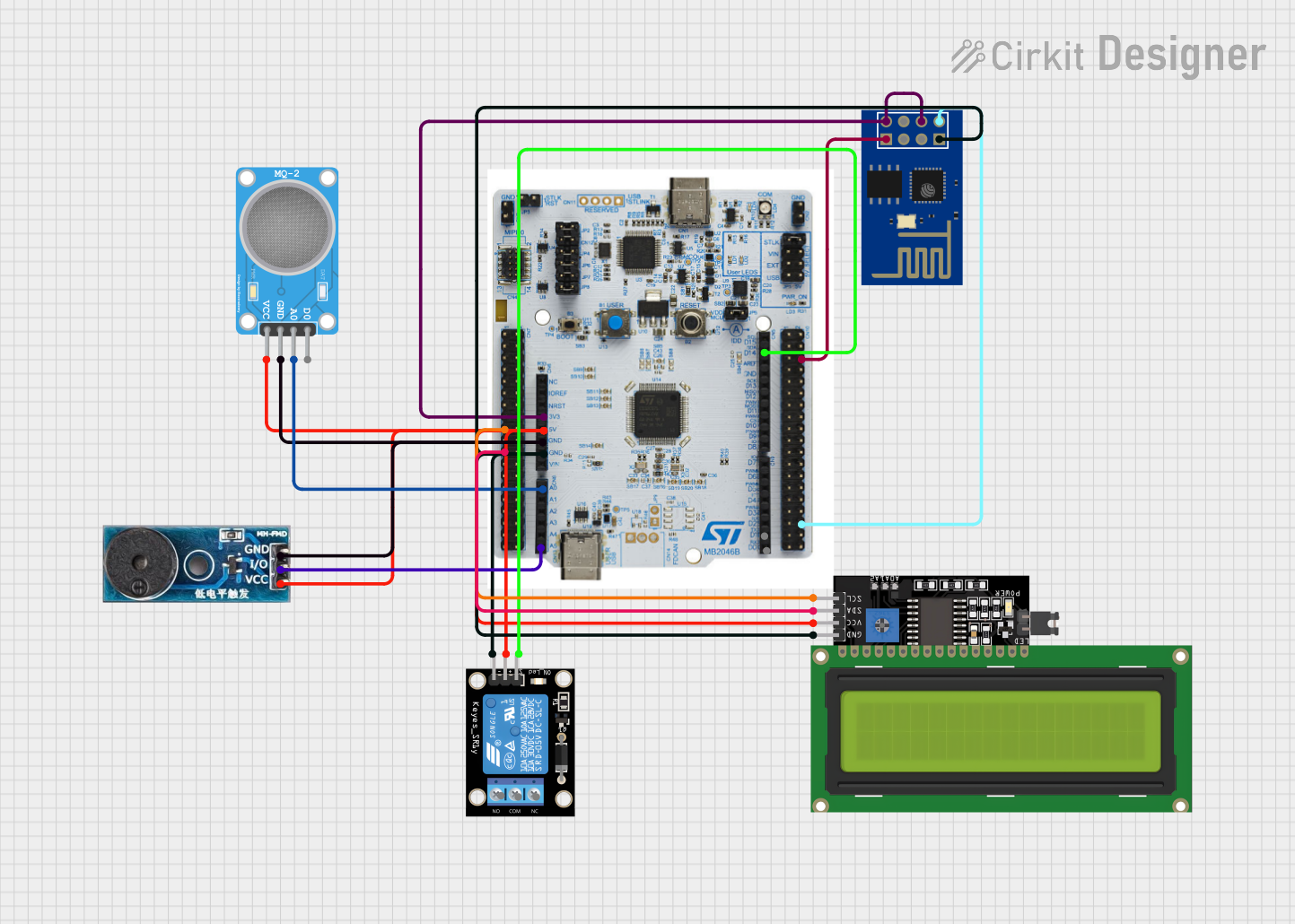

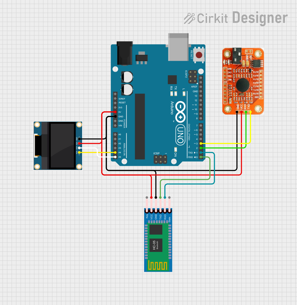

Explore Projects Built with CDI module
Common Applications and Use Cases
- Motorcycles, scooters, and small engine vehicles
- Lawn mowers, chainsaws, and other small machinery
- High-performance racing engines
- Marine engines and outboard motors
- Hobbyist and DIY engine projects
Technical Specifications
The following table outlines the key technical details of the Adafruit Industries CDI module (Part ID: 4546):
| Parameter | Value |
|---|---|
| Input Voltage Range | 6V to 12V DC |
| Output Voltage (Spark) | Up to 40kV |
| Maximum Current Draw | 2A |
| Capacitor Charge Time | < 1ms |
| Operating Temperature | -20°C to 85°C |
| Dimensions | 50mm x 30mm x 20mm |
| Weight | 45g |
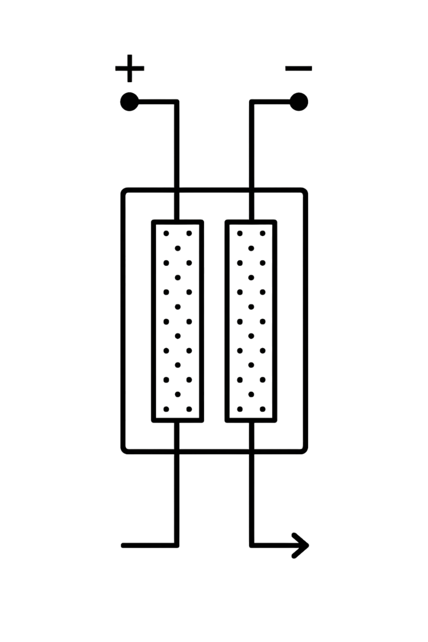
Pin Configuration and Descriptions
The CDI module has a simple pinout for easy integration into ignition systems. The table below describes each pin:
| Pin Name | Pin Number | Description |
|---|---|---|
| VIN | 1 | Input voltage (6V to 12V DC) |
| GND | 2 | Ground connection |
| TRIG | 3 | Trigger input for ignition timing (e.g., from a sensor) |
| COIL+ | 4 | Positive output to the ignition coil |
| COIL- | 5 | Negative output to the ignition coil |
Usage Instructions
How to Use the CDI Module in a Circuit
- Power Supply: Connect the VIN pin to a stable DC power source (6V to 12V) and the GND pin to the ground of your circuit.
- Trigger Input: Connect the TRIG pin to the output of a timing sensor (e.g., Hall effect sensor or crankshaft position sensor). This input determines the ignition timing.
- Ignition Coil: Connect the COIL+ and COIL- pins to the primary winding of the ignition coil. Ensure proper polarity to avoid damage.
- Spark Plug: The high-voltage output from the ignition coil should be connected to the spark plug.
Important Considerations and Best Practices
- Voltage Compatibility: Ensure the input voltage is within the specified range (6V to 12V DC). Exceeding this range may damage the module.
- Heat Dissipation: Install the module in a well-ventilated area to prevent overheating during operation.
- Trigger Signal: Use a clean and stable trigger signal to ensure accurate ignition timing.
- Wiring: Use high-quality, insulated wires to handle the high-voltage output safely.
- Testing: Before connecting to an engine, test the module with a dummy load (e.g., a test spark gap) to verify functionality.
Example Code for Arduino UNO Integration
The CDI module can be triggered using an Arduino UNO to simulate ignition timing. Below is an example code snippet:
// Example code to trigger the CDI module using an Arduino UNO
// This code generates a pulse on pin 7 to simulate ignition timing

const int triggerPin = 7; // Pin connected to the TRIG pin of the CDI module
const int pulseInterval = 100; // Time between pulses in milliseconds

void setup() {
  pinMode(triggerPin, OUTPUT); // Set the trigger pin as an output
}

void loop() {
  digitalWrite(triggerPin, HIGH); // Send a HIGH signal to trigger the CDI
  delay(1); // Keep the pulse duration short (1ms)
  digitalWrite(triggerPin, LOW); // Set the pin LOW to end the pulse
  delay(pulseInterval); // Wait before sending the next pulse
}
Note: Adjust the
pulseIntervalvariable to match the desired engine RPM. For example, a shorter interval corresponds to a higher RPM.
Troubleshooting and FAQs
Common Issues and Solutions
No Spark Output
- Cause: Incorrect wiring or insufficient input voltage.
- Solution: Verify all connections and ensure the input voltage is within the specified range.
Overheating
- Cause: Prolonged operation in a poorly ventilated area.
- Solution: Install the module in a location with adequate airflow or use a heat sink.
Erratic Ignition Timing
- Cause: Unstable or noisy trigger signal.
- Solution: Use a shielded cable for the trigger input and ensure the sensor is functioning correctly.
Module Not Powering On
- Cause: Faulty power supply or reversed polarity.
- Solution: Check the power supply and ensure correct polarity for the VIN and GND pins.
FAQs
Q: Can the CDI module be used with a 24V power supply?
A: No, the module is designed for a maximum input voltage of 12V. Using a 24V supply may damage the module.
Q: Is the module compatible with all ignition coils?
A: The module is compatible with most standard ignition coils. However, ensure the coil's primary winding resistance is within the recommended range (typically 0.5Ω to 3Ω).
Q: Can I use the module for a multi-cylinder engine?
A: The module is designed for single-cylinder engines. For multi-cylinder engines, multiple modules or a specialized multi-channel CDI system is required.
Q: How do I test the module without an engine?
A: Connect the module to a power supply and use a signal generator or Arduino to provide a trigger signal. Observe the spark output using a test spark gap.
By following this documentation, users can effectively integrate and troubleshoot the Adafruit Industries CDI module (Part ID: 4546) in their projects.