Cirkit Designer
Your all-in-one circuit design IDE
Home /
Component Documentation
How to Use MDDS30 A CYTRON MOTER DRIVER: Examples, Pinouts, and Specs
Introduction
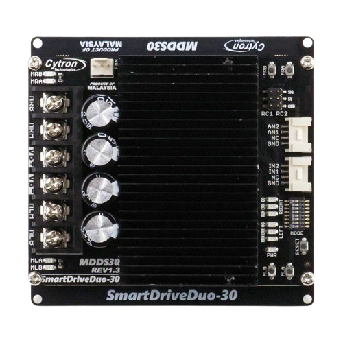
The MDDS30 Cytron Motor Driver is a robust module designed for controlling two DC motors with directional and speed control capabilities. It is suitable for a variety of applications, including robotics, electric vehicles, and automation systems. The driver accepts a wide range of input voltages and uses Pulse Width Modulation (PWM) for precise control over motor speed.
Explore Projects Built with MDDS30 A CYTRON MOTER DRIVER
Battery-Powered Remote-Controlled Dual Motor System with Cytron URC10

This circuit is a remote-controlled dual DC motor driver system powered by a 3S LiPo battery. It uses a Cytron URC10 motor driver to control two GM25 DC motors based on signals received from an R6FG receiver, with a rocker switch for power control and a 7-segment panel voltmeter for monitoring the battery voltage.
Battery-Powered Motor Control System with FlySky Receiver and Cytron Motor Driver
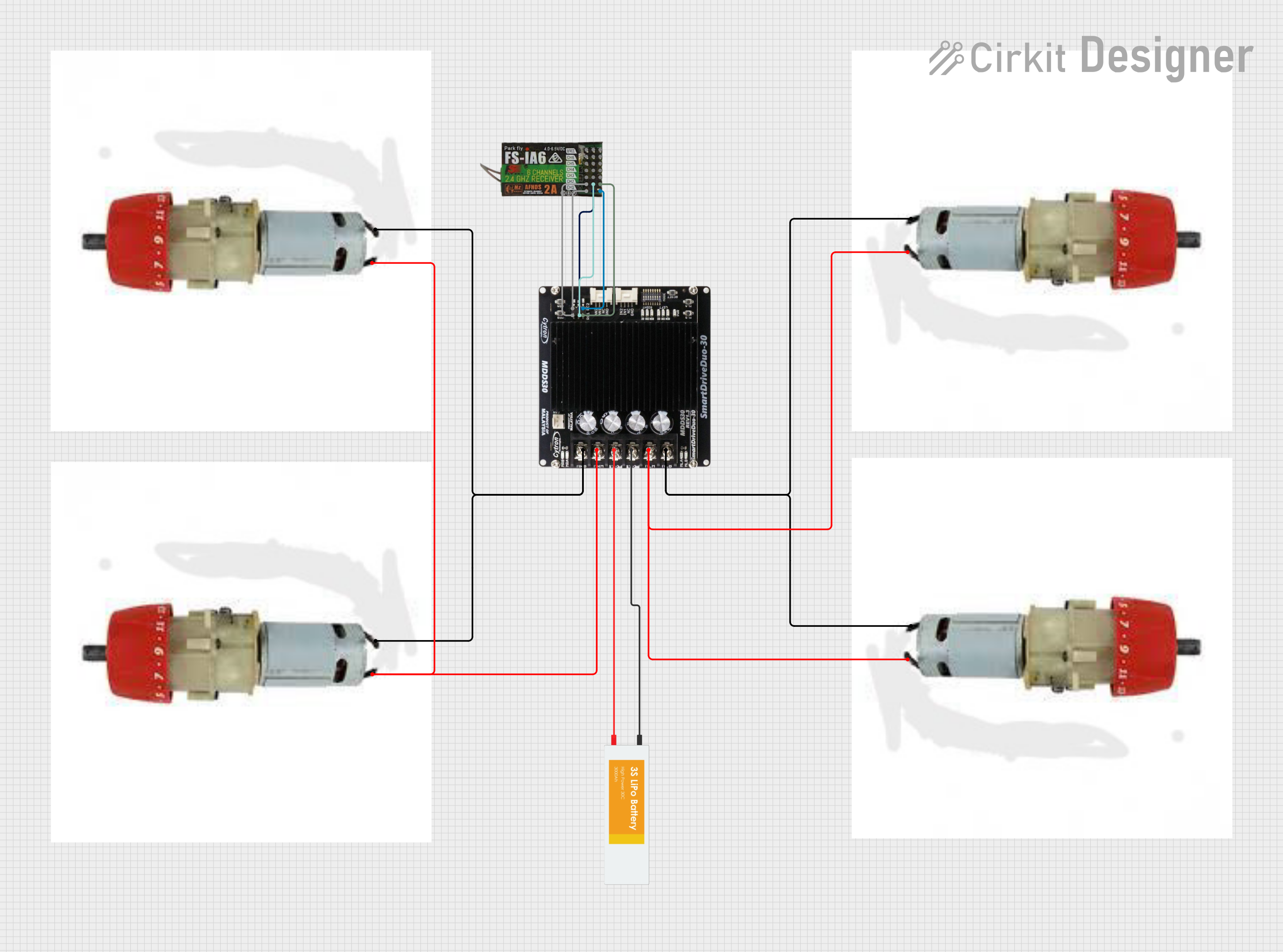
The circuit is a motor control system that uses a FlySky FS-IA6 receiver to control four motors via a Cytron MDDS30 motor driver. The system is powered by a LiPo battery, and the receiver sends control signals to the motor driver, which then drives the motors accordingly.
Battery-Powered Line Following Robot with IR Sensors and Cytron URC10 Motor Controller

This circuit is a robotic control system that uses multiple IR sensors for line detection and obstacle avoidance, powered by a 3S LiPo battery. The Cytron URC10 motor driver, controlled by a microcontroller, drives two GM25 DC motors based on input from the sensors and a rocker switch, with a 7-segment panel voltmeter displaying the battery voltage.
Semi-Autonomous GPS-Navigated Wheelchair with Obstacle Avoidance and Joystick Control

This circuit is designed for a semi-autonomous wheelchair addon that uses two 24V DC motors for propulsion, controlled by a Cytron motor driver. It features three HC-SR04 ultrasonic sensors for obstacle detection, a GPS module for navigation, and an analog thumbstick for manual control. The system is managed by an Arduino Mega 2560, which processes sensor inputs, controls motor outputs, and interfaces with an LCD display for user feedback, a buzzer for alerts, and a set of push buttons for additional input commands.
Explore Projects Built with MDDS30 A CYTRON MOTER DRIVER
Battery-Powered Remote-Controlled Dual Motor System with Cytron URC10
This circuit is a remote-controlled dual DC motor driver system powered by a 3S LiPo battery. It uses a Cytron URC10 motor driver to control two GM25 DC motors based on signals received from an R6FG receiver, with a rocker switch for power control and a 7-segment panel voltmeter for monitoring the battery voltage.
Battery-Powered Motor Control System with FlySky Receiver and Cytron Motor Driver
The circuit is a motor control system that uses a FlySky FS-IA6 receiver to control four motors via a Cytron MDDS30 motor driver. The system is powered by a LiPo battery, and the receiver sends control signals to the motor driver, which then drives the motors accordingly.
Battery-Powered Line Following Robot with IR Sensors and Cytron URC10 Motor Controller
This circuit is a robotic control system that uses multiple IR sensors for line detection and obstacle avoidance, powered by a 3S LiPo battery. The Cytron URC10 motor driver, controlled by a microcontroller, drives two GM25 DC motors based on input from the sensors and a rocker switch, with a 7-segment panel voltmeter displaying the battery voltage.
Semi-Autonomous GPS-Navigated Wheelchair with Obstacle Avoidance and Joystick Control
This circuit is designed for a semi-autonomous wheelchair addon that uses two 24V DC motors for propulsion, controlled by a Cytron motor driver. It features three HC-SR04 ultrasonic sensors for obstacle detection, a GPS module for navigation, and an analog thumbstick for manual control. The system is managed by an Arduino Mega 2560, which processes sensor inputs, controls motor outputs, and interfaces with an LCD display for user feedback, a buzzer for alerts, and a set of push buttons for additional input commands.
Common Applications and Use Cases
- Robotics: Driving wheels or tracks on robotic vehicles.
- Automation: Controlling conveyor belts, linear actuators, or other machinery.
- Electric Vehicles: Managing propulsion and steering systems.
- Hobby Projects: DIY projects requiring motor control, such as RC cars or boats.
Technical Specifications
Key Technical Details
- Operating Voltage: 7V to 35V
- Continuous Current: Up to 30A per channel
- Peak Current: 80A (maximum 10 seconds per minute)
- Logic Input Voltage: 3.3V to 5V
- PWM Frequency: Up to 20kHz
- Control Signal: PWM and Direction inputs
Pin Configuration and Descriptions
| Pin Name | Description |
|---|---|
| V+ | Motor power supply input (7V to 35V) |
| GND | Ground connection |
| M1A, M1B | Motor 1 output terminals |
| M2A, M2B | Motor 2 output terminals |
| PWM1 | PWM input for Motor 1 speed control |
| DIR1 | Direction input for Motor 1 |
| PWM2 | PWM input for Motor 2 speed control |
| DIR2 | Direction input for Motor 2 |
| AN1 | Analog input for Motor 1 speed control (alternative to PWM1) |
| AN2 | Analog input for Motor 2 speed control (alternative to PWM2) |
| EN | Enable input (active HIGH) |
Usage Instructions
How to Use the Component in a Circuit
Power Connections:
- Connect the motor power supply to the V+ and GND terminals.
- Ensure the power supply voltage is within the specified range (7V to 35V).
Motor Connections:
- Connect the terminals of Motor 1 to M1A and M1B.
- Connect the terminals of Motor 2 to M2A and M2B.
Control Signal Connections:
- Connect the PWM signal for Motor 1 to PWM1 and the direction signal to DIR1.
- Connect the PWM signal for Motor 2 to PWM2 and the direction signal to DIR2.
- Alternatively, use AN1 and AN2 for analog speed control.
Enable the Driver:
- Connect the EN pin to a logic HIGH signal to enable the driver.
Important Considerations and Best Practices
- Ensure that the power supply can handle the current requirements of your motors.
- Use appropriate gauge wires for the motor and power connections to handle the current draw.
- Always provide a proper heat dissipation mechanism for the driver when operating at high currents.
- Avoid running the motor driver at its peak current for extended periods to prevent overheating and damage.
- Implement an emergency stop mechanism to quickly disable the motor driver in case of malfunction.
Troubleshooting and FAQs
Common Issues Users Might Face
- Motor not running: Check power supply connections, ensure the EN pin is set to HIGH, and verify that the PWM and DIR signals are being sent correctly.
- Overheating: Ensure proper heat dissipation, check for overcurrent conditions, and verify that the duty cycle of the PWM signal is not too high for extended periods.
- Erratic motor behavior: Confirm that the PWM frequency is within the specified range and that the control signals are not noisy.
Solutions and Tips for Troubleshooting
- Motor not running: Double-check wiring and signal connections. Use a multimeter to verify the presence of voltage at the motor terminals.
- Overheating: Attach a heatsink or fan to the motor driver, reduce the load on the motors, or decrease the duty cycle of the PWM signal.
- Erratic motor behavior: Use a shorter cable for the control signals, add a decoupling capacitor close to the motor driver, or shield the cables to reduce noise.
Example Code for Arduino UNO
// Example code to control a motor using the MDDS30 Cytron Motor Driver
#include <Arduino.h>

// Define control pins
const int pwmPin1 = 3; // PWM input for Motor 1
const int dirPin1 = 4; // Direction input for Motor 1

void setup() {
  // Set control pins as outputs
  pinMode(pwmPin1, OUTPUT);
  pinMode(dirPin1, OUTPUT);
}

void loop() {
  // Set Motor 1 direction to forward
  digitalWrite(dirPin1, HIGH);

  // Ramp up the speed
  for (int speed = 0; speed <= 255; speed++) {
    analogWrite(pwmPin1, speed);
    delay(10);
  }

  // Ramp down the speed
  for (int speed = 255; speed >= 0; speed--) {
    analogWrite(pwmPin1, speed);
    delay(10);
  }

  // Change direction to reverse
  digitalWrite(dirPin1, LOW);

  // Repeat the ramp up and down with reverse direction
  for (int speed = 0; speed <= 255; speed++) {
    analogWrite(pwmPin1, speed);
    delay(10);
  }

  for (int speed = 255; speed >= 0; speed--) {
    analogWrite(pwmPin1, speed);
    delay(10);
  }
}
Note: The above code is a simple demonstration of controlling a motor's speed and direction using PWM. Adjust the pwmPin1 and dirPin1 variables to match your actual control pin connections on the Arduino UNO.