How to Use LORA_RA02: Examples, Pinouts, and Specs
Introduction
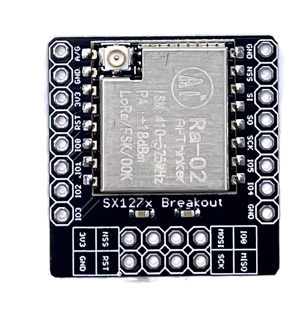
The LORA_RA02 is a LoRa (Long Range) transceiver module that enables long-distance wireless communication with low power consumption. This module is based on the SX1278 IC and operates in the 433MHz frequency band. It is widely used in Internet of Things (IoT) applications, such as remote environmental monitoring, smart agriculture, home automation, and wireless sensor networks.
Explore Projects Built with LORA_RA02
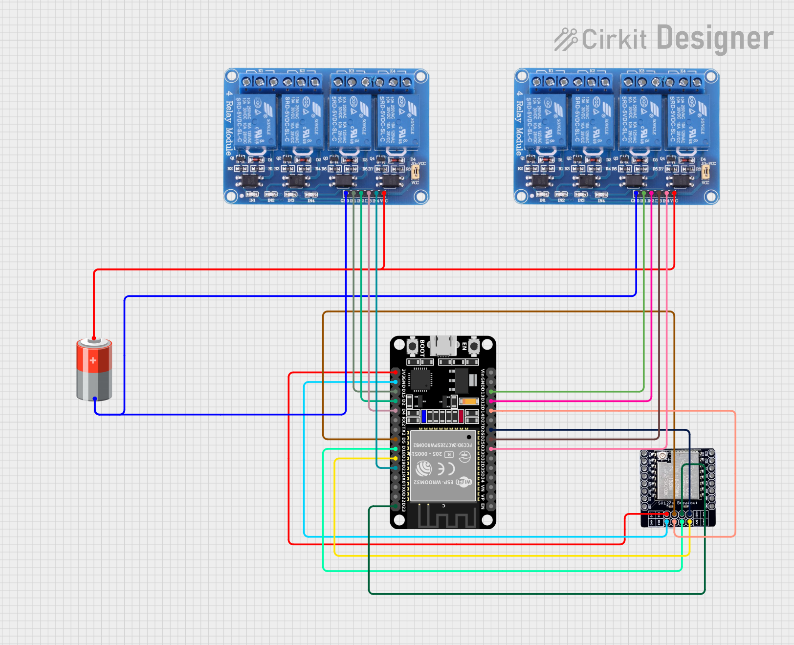
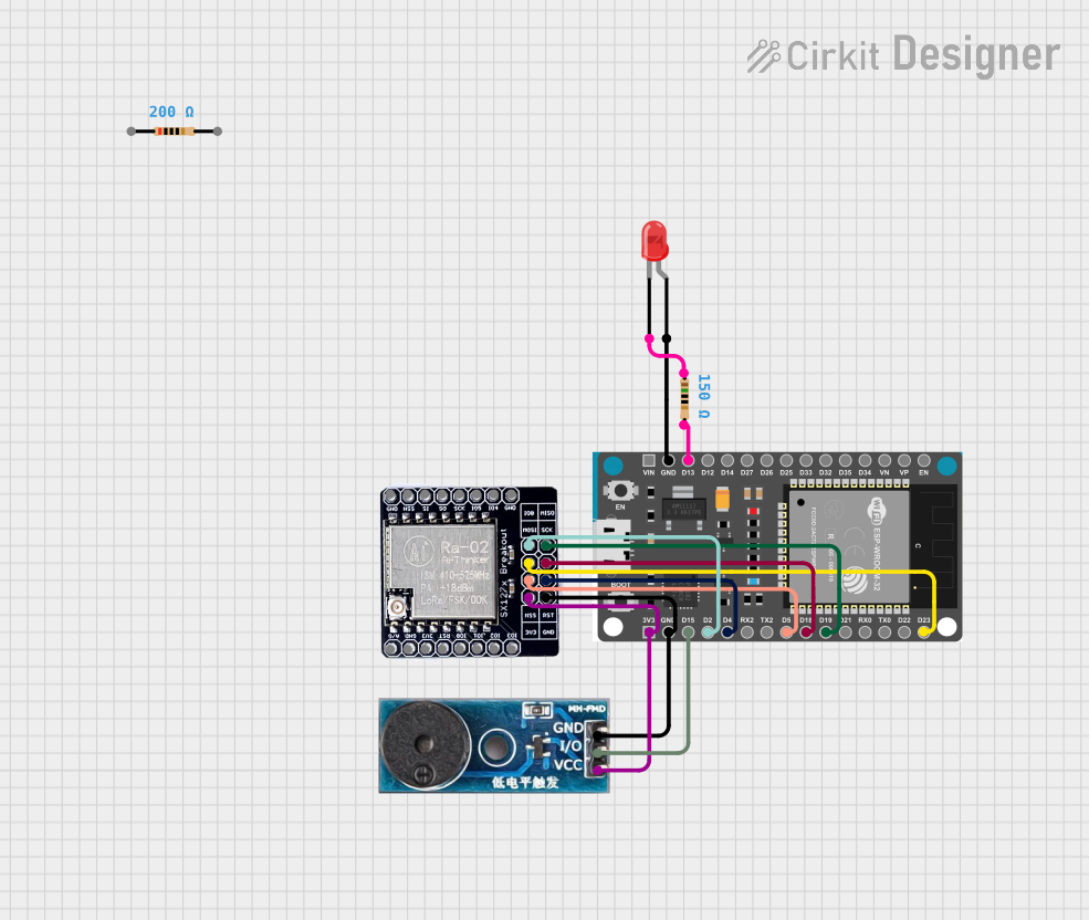


Explore Projects Built with LORA_RA02
Common Applications and Use Cases
- Remote sensor data collection
- Smart agriculture and irrigation systems
- Home and industrial automation
- Asset tracking and logistics
- Smart city infrastructure
Technical Specifications
Key Technical Details
- Frequency Range: 433 MHz
- Modulation: LoRa Spread Spectrum
- Output Power: +20 dBm - 100 mW
- Sensitivity: -139 dBm at SF12 and 62.5KHz
- Data Transfer Rate: 0.018 kbps - 37.5 kbps
- Operating Voltage: 1.8 - 3.7 V
- Operating Temperature Range: -40°C to +85°C
Pin Configuration and Descriptions
| Pin Number | Name | Description |
|---|---|---|
| 1 | GND | Ground connection |
| 2 | 3.3V | Power supply (3.3V) |
| 3 | NSS | SPI Chip Select |
| 4 | SCK | SPI Clock |
| 5 | MOSI | SPI Master Out Slave In |
| 6 | MISO | SPI Master In Slave Out |
| 7 | DIO0 | Digital I/O (used for interrupt signaling) |
| 8 | RST | Reset pin |
| 9 | ANT | Antenna connection |
Usage Instructions
How to Use the Component in a Circuit
- Power Supply: Connect the 3.3V and GND pins to a stable 3.3V power source.
- SPI Interface: Connect the NSS, SCK, MOSI, and MISO pins to the corresponding SPI interface pins of the microcontroller.
- Interrupts: Connect the DIO0 pin to an interrupt-capable GPIO pin on the microcontroller.
- Reset: Connect the RST pin to a GPIO pin on the microcontroller for module reset control.
- Antenna: Attach an appropriate 433MHz antenna to the ANT pin for signal transmission and reception.
Important Considerations and Best Practices
- Ensure that the power supply is clean and stable to prevent module malfunction.
- Use impedance-matched antenna to maximize communication range.
- Keep the antenna area clear of metal objects and electronic interference.
- Follow local regulations regarding the use of the 433MHz frequency band.
- Implement proper error-checking and handling mechanisms in your communication protocol.
Example Code for Arduino UNO
#include <SPI.h>
#include <LoRa.h>

// Define the LoRa module pins
#define SS_PIN   10
#define RST_PIN  9
#define DIO0_PIN 2

void setup() {
  // Initialize LoRa module
  LoRa.setPins(SS_PIN, RST_PIN, DIO0_PIN);
  if (!LoRa.begin(433E6)) {
    Serial.println("Starting LoRa failed!");
    while (1);
  }
}

void loop() {
  // Send a message
  LoRa.beginPacket();
  LoRa.print("Hello, LoRa!");
  LoRa.endPacket();

  // Wait for a second before sending the next message
  delay(1000);
}
Troubleshooting and FAQs
Common Issues Users Might Face
- No Communication: Ensure that the antenna is properly connected and the module is correctly powered.
- Short Range: Check for obstacles or interference sources. Verify that the antenna is suitable for the 433MHz band.
- Intermittent Communication: Make sure the SPI connections are secure and the power supply is stable.
Solutions and Tips for Troubleshooting
- Power Issues: Use a multimeter to verify the voltage at the power supply pin.
- SPI Issues: Use an oscilloscope to check the SPI signals for proper operation.
- Antenna Issues: Test with a known good antenna and ensure it is properly oriented.
FAQs
Q: Can I use the LORA_RA02 with a 5V microcontroller? A: Yes, but ensure that the logic level for the SPI interface is shifted down to 3.3V to avoid damaging the module.
Q: How can I increase the communication range? A: Use a high-gain antenna, reduce data rate, increase transmit power, and ensure line-of-sight where possible.
Q: What is the maximum power supply voltage for the LORA_RA02? A: The maximum voltage is 3.7V. Exceeding this voltage can permanently damage the module.
Q: Is it necessary to use an external antenna? A: Yes, an external antenna is required for the module to transmit and receive signals effectively.
This documentation provides a comprehensive guide to the LORA_RA02 module, ensuring users can effectively integrate it into their projects. For further assistance, consult the manufacturer's datasheet and technical support resources.