Cirkit Designer Logo
Cirkit Designer
Your all-in-one circuit design IDE
Home / 
Component Documentation

How to Use WiFi Single Relay Module ESP DC5-80V Wireless Controller Relay Module Board: Examples, Pinouts, and Specs

Image of WiFi Single Relay Module ESP DC5-80V Wireless Controller Relay Module Board
Cirkit Designer LogoDesign with WiFi Single Relay Module ESP DC5-80V Wireless Controller Relay Module Board in Cirkit Designer

Introduction

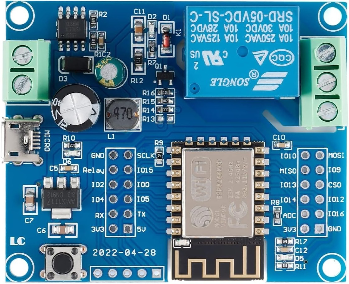
The WiFi Single Relay Module ESP DC5-80V Wireless Controller Relay Module Board (Manufacturer: JESSINIE, Part ID: ESP-12F) is a versatile wireless relay module designed for remote control of electrical devices via WiFi. It integrates seamlessly with ESP8266/ESP32 microcontrollers, making it an ideal choice for IoT and home automation projects. This module supports a wide DC voltage range of 5-80V, providing flexibility for various applications.

Explore Projects Built with WiFi Single Relay Module ESP DC5-80V Wireless Controller Relay Module Board

Use Cirkit Designer to design, explore, and prototype these projects online. Some projects support real-time simulation. Click "Open Project" to start designing instantly!
Wi-Fi Controlled Relay Module with ESP8266 and MCP23017
Image of smart home: A project utilizing WiFi Single Relay Module ESP DC5-80V Wireless Controller Relay Module Board in a practical application
This circuit is a WiFi-enabled relay control system using an ESP8266-01 module and an MCP23017 I/O expander. The ESP8266 communicates with the MCP23017 via I2C to control an 8-channel relay module based on the state of 8 rocker switches, allowing for remote and manual control of connected devices.
Cirkit Designer LogoOpen Project in Cirkit Designer
ESP8266 NodeMCU Based Solar-Powered Relay Control System
Image of home automation : A project utilizing WiFi Single Relay Module ESP DC5-80V Wireless Controller Relay Module Board in a practical application
This circuit features an ESP8266 NodeMCU microcontroller interfaced with a 4-channel relay module, allowing for control of external devices. The ESP8266's GPIO pins are connected to the relay inputs and pushbuttons for user interaction. Power management is handled by a TP4056 charging module connected to a pair of 18650 Li-ion batteries, with input from a solar panel through a 1N4007 diode for protection and a 7805 voltage regulator ensuring stable 5V supply to the system.
Cirkit Designer LogoOpen Project in Cirkit Designer
Wi-Fi Controlled Relay System Using ESP8266
Image of Smart House Automation: A project utilizing WiFi Single Relay Module ESP DC5-80V Wireless Controller Relay Module Board in a practical application
This circuit uses an ESP8266 microcontroller to control a 4-channel relay module, which can switch various loads. The ESP8266 is powered by a 12V DC supply converted from an AC source, and it interfaces with the relay module to control the relays via its digital output pins.
Cirkit Designer LogoOpen Project in Cirkit Designer
Wi-Fi Controlled 4-Channel Relay System with Arduino and ESP8266
Image of Wi-Fi Controlled 4-Channel Relay with Arduino and ESP8266: A project utilizing WiFi Single Relay Module ESP DC5-80V Wireless Controller Relay Module Board in a practical application
This circuit is a Wi-Fi controlled 4-channel relay system using an Arduino UNO and an ESP8266 module. The relays can be controlled via a web interface served by the ESP8266, and the status of each relay is displayed on a 16x4 I2C LCD. The relays are used to control four 220V AC red lights, and the Arduino communicates with the ESP8266 via serial communication.
Cirkit Designer LogoOpen Project in Cirkit Designer

Explore Projects Built with WiFi Single Relay Module ESP DC5-80V Wireless Controller Relay Module Board

Use Cirkit Designer to design, explore, and prototype these projects online. Some projects support real-time simulation. Click "Open Project" to start designing instantly!
Image of smart home: A project utilizing WiFi Single Relay Module ESP DC5-80V Wireless Controller Relay Module Board in a practical application
Wi-Fi Controlled Relay Module with ESP8266 and MCP23017
This circuit is a WiFi-enabled relay control system using an ESP8266-01 module and an MCP23017 I/O expander. The ESP8266 communicates with the MCP23017 via I2C to control an 8-channel relay module based on the state of 8 rocker switches, allowing for remote and manual control of connected devices.
Cirkit Designer LogoOpen Project in Cirkit Designer
Image of home automation : A project utilizing WiFi Single Relay Module ESP DC5-80V Wireless Controller Relay Module Board in a practical application
ESP8266 NodeMCU Based Solar-Powered Relay Control System
This circuit features an ESP8266 NodeMCU microcontroller interfaced with a 4-channel relay module, allowing for control of external devices. The ESP8266's GPIO pins are connected to the relay inputs and pushbuttons for user interaction. Power management is handled by a TP4056 charging module connected to a pair of 18650 Li-ion batteries, with input from a solar panel through a 1N4007 diode for protection and a 7805 voltage regulator ensuring stable 5V supply to the system.
Cirkit Designer LogoOpen Project in Cirkit Designer
Image of Smart House Automation: A project utilizing WiFi Single Relay Module ESP DC5-80V Wireless Controller Relay Module Board in a practical application
Wi-Fi Controlled Relay System Using ESP8266
This circuit uses an ESP8266 microcontroller to control a 4-channel relay module, which can switch various loads. The ESP8266 is powered by a 12V DC supply converted from an AC source, and it interfaces with the relay module to control the relays via its digital output pins.
Cirkit Designer LogoOpen Project in Cirkit Designer
Image of Wi-Fi Controlled 4-Channel Relay with Arduino and ESP8266: A project utilizing WiFi Single Relay Module ESP DC5-80V Wireless Controller Relay Module Board in a practical application
Wi-Fi Controlled 4-Channel Relay System with Arduino and ESP8266
This circuit is a Wi-Fi controlled 4-channel relay system using an Arduino UNO and an ESP8266 module. The relays can be controlled via a web interface served by the ESP8266, and the status of each relay is displayed on a 16x4 I2C LCD. The relays are used to control four 220V AC red lights, and the Arduino communicates with the ESP8266 via serial communication.
Cirkit Designer LogoOpen Project in Cirkit Designer

Common Applications and Use Cases

  • Home automation (e.g., controlling lights, fans, or appliances remotely)
  • Industrial automation and control systems
  • IoT projects requiring wireless relay control
  • Smart agriculture systems (e.g., irrigation control)
  • Remote switching of low-power or high-power devices

Technical Specifications

Below are the key technical details and pin configuration for the module:

Key Technical Details

Parameter Specification
Operating Voltage DC 5-80V
Relay Type Single-channel relay
Wireless Protocol WiFi (2.4 GHz, IEEE 802.11 b/g/n)
Microcontroller Support ESP8266/ESP32
Relay Control Voltage 3.3V (logic high)
Maximum Load Current 10A
Maximum Load Voltage 250V AC / 30V DC
Dimensions 50mm x 25mm x 18mm
Operating Temperature -40°C to 85°C

Pin Configuration and Descriptions

Pin Name Description
VCC Power input pin (DC 5-80V)
GND Ground pin
IN Control signal input pin (connects to ESP8266/ESP32 GPIO pin)
NO Normally Open terminal of the relay (connects to the load when activated)
COM Common terminal of the relay
NC Normally Closed terminal of the relay (connects to the load when inactive)

Usage Instructions

How to Use the Component in a Circuit

  1. Power the Module: Connect the VCC pin to a DC power source (5-80V) and the GND pin to ground.
  2. Connect the Load:
    • For devices that should be powered when the relay is active, connect the load between the NO (Normally Open) and COM (Common) terminals.
    • For devices that should be powered when the relay is inactive, connect the load between the NC (Normally Closed) and COM terminals.
  3. Control the Relay: Connect the IN pin to a GPIO pin of an ESP8266/ESP32 microcontroller. When the GPIO pin outputs a HIGH signal (3.3V), the relay will activate, switching the load.
  4. Program the Microcontroller: Use the provided code example to control the relay via WiFi.

Important Considerations and Best Practices

  • Ensure the load current and voltage do not exceed the relay's maximum ratings (10A, 250V AC / 30V DC).
  • Use proper insulation and safety precautions when working with high-voltage loads.
  • Avoid rapid switching of the relay to prevent wear and tear on the mechanical components.
  • Use a flyback diode across inductive loads (e.g., motors) to protect the relay from voltage spikes.

Example Code for Arduino UNO with ESP8266

Below is an example code to control the relay module using an ESP8266 microcontroller:

#include <ESP8266WiFi.h>

// Replace with your network credentials
const char* ssid = "Your_SSID";
const char* password = "Your_PASSWORD";

// Define the GPIO pin connected to the relay module
#define RELAY_PIN D1

void setup() {
  // Initialize serial communication for debugging
  Serial.begin(115200);

  // Set the relay pin as an output
  pinMode(RELAY_PIN, OUTPUT);

  // Start with the relay off
  digitalWrite(RELAY_PIN, LOW);

  // Connect to WiFi
  Serial.print("Connecting to WiFi...");
  WiFi.begin(ssid, password);
  while (WiFi.status() != WL_CONNECTED) {
    delay(500);
    Serial.print(".");
  }
  Serial.println("\nWiFi connected!");
}

void loop() {
  // Example: Turn the relay on for 5 seconds, then off for 5 seconds
  Serial.println("Relay ON");
  digitalWrite(RELAY_PIN, HIGH); // Activate the relay
  delay(5000);                  // Wait for 5 seconds

  Serial.println("Relay OFF");
  digitalWrite(RELAY_PIN, LOW); // Deactivate the relay
  delay(5000);                  // Wait for 5 seconds
}

Troubleshooting and FAQs

Common Issues and Solutions

  1. Relay Not Activating:

    • Ensure the IN pin is receiving a 3.3V HIGH signal from the microcontroller.
    • Verify that the VCC and GND pins are properly connected to a power source.
  2. WiFi Connection Fails:

    • Double-check the SSID and password in the code.
    • Ensure the ESP8266 is within range of the WiFi router.
  3. Load Not Switching:

    • Confirm that the load is connected to the correct relay terminals (NO/NC and COM).
    • Check that the load's voltage and current are within the relay's rated limits.
  4. Module Overheating:

    • Ensure the load does not exceed the relay's maximum current rating (10A).
    • Provide adequate ventilation around the module.

FAQs

Q1: Can this module be used with a 5V microcontroller like Arduino UNO?
A1: Yes, but you will need a level shifter or a transistor circuit to step down the 5V control signal to 3.3V for the IN pin.

Q2: Is this module compatible with MQTT or other IoT protocols?
A2: Yes, when paired with an ESP8266/ESP32, you can use libraries like PubSubClient to implement MQTT or other IoT protocols.

Q3: Can I control the relay over the internet?
A3: Yes, by configuring the ESP8266/ESP32 for internet connectivity, you can control the relay remotely via a web server or cloud platform.

Q4: What happens if the power supply exceeds 80V?
A4: Exceeding the maximum voltage rating can damage the module. Always use a regulated power supply within the specified range (5-80V).