How to Use 테무 콘트롤 전원 스위치 듀얼 AC, DC 타입: Examples, Pinouts, and Specs
Introduction
The 테무 콘트롤 전원 스위치 듀얼 AC, DC 타입 is a versatile power control switch designed to manage power supply in electronic circuits. It allows seamless switching between alternating current (AC) and direct current (DC) sources, making it ideal for applications requiring dual power input options. This component is particularly useful in systems where both AC and DC power sources are available, such as backup power systems, hybrid power systems, and industrial control circuits.
Explore Projects Built with 테무 콘트롤 전원 스위치 듀얼 AC, DC 타입
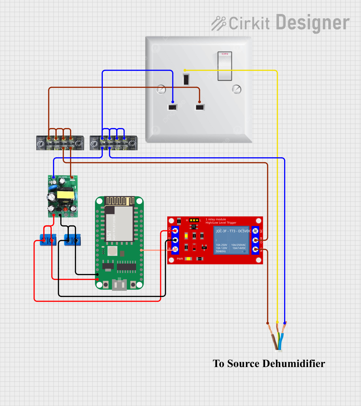
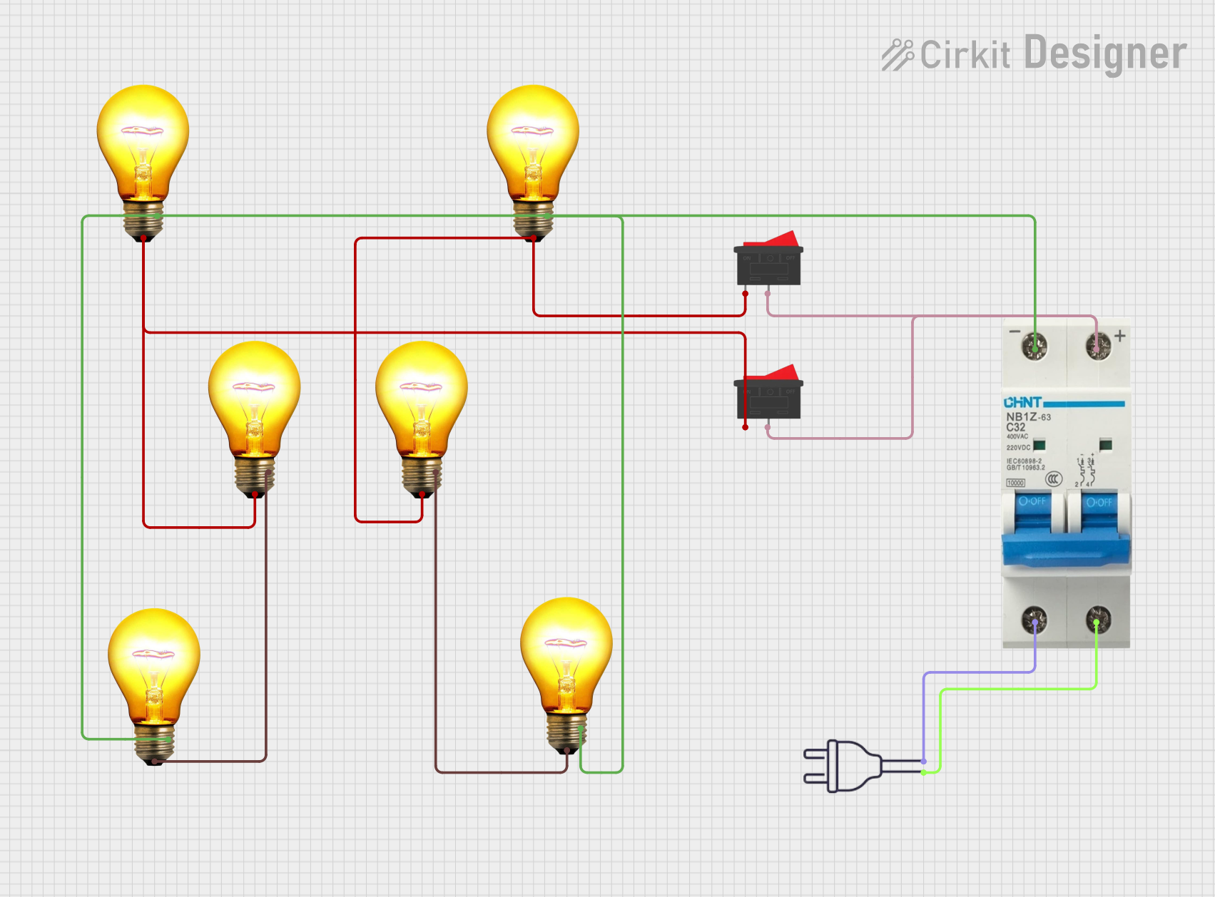


Explore Projects Built with 테무 콘트롤 전원 스위치 듀얼 AC, DC 타입
Common Applications and Use Cases
- Backup power systems with AC and DC inputs
- Hybrid power systems in renewable energy setups
- Industrial control circuits requiring dual power source management
- Home automation systems with mixed power sources
- Prototyping and testing circuits with AC/DC power requirements
Technical Specifications
Below are the key technical details for the 테무 콘트롤 전원 스위치 듀얼 AC, DC 타입:
General Specifications
| Parameter | Value |
|---|---|
| Manufacturer | 테무 |
| Part ID | 테무 콘트롤 전원 스위치 듀얼 AC, DC 타입 |
| Input Voltage (AC) | 100V - 240V AC |
| Input Voltage (DC) | 12V - 48V DC |
| Maximum Current | 10A |
| Power Rating | 240W (DC) / 2400W (AC) |
| Switching Type | Manual or Automatic |
| Operating Temperature | -20°C to 70°C |
| Dimensions | 50mm x 30mm x 20mm |
| Mounting Type | PCB Mount |
Pin Configuration and Descriptions
The component has a total of 6 pins, as described in the table below:
| Pin Number | Pin Name | Description |
|---|---|---|
| 1 | AC_IN_L | Live input for AC power source |
| 2 | AC_IN_N | Neutral input for AC power source |
| 3 | DC_IN_POS | Positive input for DC power source |
| 4 | DC_IN_NEG | Negative input for DC power source |
| 5 | OUTPUT_POS | Positive output to the load |
| 6 | OUTPUT_NEG | Negative output to the load |
Usage Instructions
How to Use the Component in a Circuit
- Power Source Connection:
- Connect the AC power source to the
AC_IN_L(live) andAC_IN_N(neutral) pins. - Connect the DC power source to the
DC_IN_POS(positive) andDC_IN_NEG(negative) pins.
- Connect the AC power source to the
- Load Connection:
- Connect the load to the
OUTPUT_POS(positive) andOUTPUT_NEG(negative) pins.
- Connect the load to the
- Switching:
- If the switch is in manual mode, toggle the switch to select between AC and DC power sources.
- In automatic mode, the component will prioritize the AC source by default. If AC power is unavailable, it will automatically switch to the DC source.
Important Considerations and Best Practices
- Ensure that the input voltage and current do not exceed the specified ratings to avoid damage.
- Use appropriate fuses or circuit breakers for additional protection.
- Maintain proper insulation and spacing between AC and DC connections to prevent short circuits.
- For automatic mode, ensure that the AC source is stable to avoid frequent switching.
- Verify the polarity of the DC connections before powering the circuit.
Example: Connecting to an Arduino UNO
The 테무 콘트롤 전원 스위치 듀얼 AC, DC 타입 can be used to power an Arduino UNO with a dual power source. Below is an example circuit and code:
Circuit Setup
- Connect the AC power source to the
AC_IN_LandAC_IN_Npins. - Connect a 12V DC power source to the
DC_IN_POSandDC_IN_NEGpins. - Connect the
OUTPUT_POSandOUTPUT_NEGpins to the Arduino UNO's VIN and GND pins, respectively.
Arduino Code Example
// Example code to monitor power status using Arduino UNO
// This assumes a digital pin is connected to a status output pin of the switch
// (if available) to detect whether AC or DC power is active.

const int statusPin = 2; // Pin connected to the switch's status output
const int ledPin = 13;   // Built-in LED to indicate power source

void setup() {
  pinMode(statusPin, INPUT); // Set status pin as input
  pinMode(ledPin, OUTPUT);   // Set LED pin as output
  Serial.begin(9600);        // Initialize serial communication
}

void loop() {
  int powerStatus = digitalRead(statusPin); // Read power source status

  if (powerStatus == HIGH) {
    // AC power is active
    digitalWrite(ledPin, HIGH); // Turn on LED
    Serial.println("AC power is active.");
  } else {
    // DC power is active
    digitalWrite(ledPin, LOW); // Turn off LED
    Serial.println("DC power is active.");
  }

  delay(1000); // Wait for 1 second before checking again
}
Troubleshooting and FAQs
Common Issues and Solutions
No Output Power:
- Cause: Incorrect wiring or loose connections.
- Solution: Double-check all connections and ensure proper polarity for DC inputs.
Frequent Switching Between AC and DC:
- Cause: Unstable AC power source.
- Solution: Use a voltage stabilizer or ensure a stable AC power supply.
Component Overheating:
- Cause: Exceeding the maximum current or power rating.
- Solution: Reduce the load or ensure the power source is within the specified range.
Load Not Powering On:
- Cause: Incorrect load connection or insufficient power.
- Solution: Verify the load connections and ensure the power source meets the load requirements.
FAQs
Q1: Can this switch handle both AC and DC inputs simultaneously?
A1: No, the switch is designed to handle one power source at a time. It will prioritize AC in automatic mode.
Q2: Is the component suitable for outdoor use?
A2: The component is not weatherproof. Use it in a dry, indoor environment or within a protective enclosure.
Q3: Can I use this switch with a 5V DC power source?
A3: No, the minimum DC input voltage is 12V. Using a lower voltage may result in improper operation.
Q4: Does the switch have built-in surge protection?
A4: No, external surge protection is recommended for high-voltage AC inputs.