How to Use Logic Level Converter 8-channel Bi-directional: Examples, Pinouts, and Specs
Introduction
The Logic Level Converter 8-channel Bi-directional is a versatile electronic component designed to facilitate communication between devices operating at different voltage levels. It enables seamless and safe bi-directional data transfer across 8 independent channels, making it an essential tool for interfacing low-voltage microcontrollers (e.g., 3.3V) with higher-voltage peripherals (e.g., 5V).
Explore Projects Built with Logic Level Converter 8-channel Bi-directional


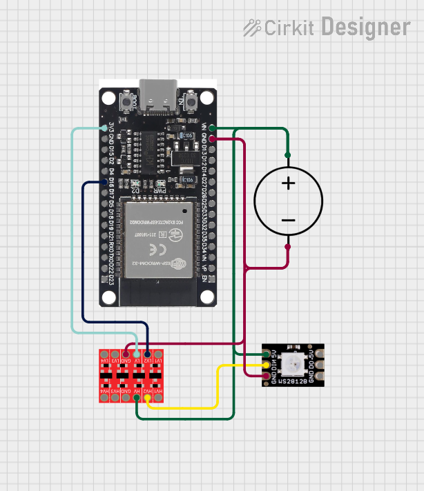
Explore Projects Built with Logic Level Converter 8-channel Bi-directional
Common Applications and Use Cases
- Interfacing 3.3V microcontrollers (e.g., Arduino, Raspberry Pi) with 5V sensors or modules.
- Communication between 1.8V, 3.3V, and 5V devices in mixed-voltage systems.
- Level shifting for I2C, SPI, UART, and other digital communication protocols.
- Prototyping and testing circuits with varying voltage requirements.
Technical Specifications
The following table outlines the key technical details of the Logic Level Converter 8-channel Bi-directional:
| Parameter | Specification |
|---|---|
| Operating Voltage (High Side) | 3.3V to 5.5V |
| Operating Voltage (Low Side) | 1.8V to 3.3V |
| Number of Channels | 8 Bi-directional |
| Communication Protocols Supported | I2C, SPI, UART, GPIO, etc. |
| Maximum Data Rate | Up to 100 kHz (I2C) or higher for GPIO |
| Dimensions | ~36mm x 20mm x 5mm |
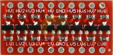
Pin Configuration and Descriptions
The Logic Level Converter has the following pin layout:
| Pin Name | Description |
|---|---|
| HV | High voltage input (connect to the higher voltage, e.g., 5V). |
| LV | Low voltage input (connect to the lower voltage, e.g., 3.3V). |
| GND | Ground (common ground for both high and low voltage sides). |
| TX1-TX8 | High voltage side data pins (connect to the high-voltage device). |
| RX1-RX8 | Low voltage side data pins (connect to the low-voltage device). |
Usage Instructions
How to Use the Component in a Circuit
Power Connections:
- Connect the
HVpin to the high voltage supply (e.g., 5V). - Connect the
LVpin to the low voltage supply (e.g., 3.3V). - Connect the
GNDpin to the common ground of both voltage domains.
- Connect the
Data Connections:
- For each channel, connect the high-voltage device's data line to the corresponding
TXpin. - Connect the low-voltage device's data line to the corresponding
RXpin. - Repeat for all channels as needed.
- For each channel, connect the high-voltage device's data line to the corresponding
Communication Protocols:
- The converter supports I2C, SPI, UART, and GPIO. Ensure proper pull-up resistors are used for I2C communication.
Important Considerations and Best Practices
- Voltage Compatibility: Ensure the
HVandLVvoltages are within the specified ranges. - Pull-up Resistors: For I2C communication, use appropriate pull-up resistors on both the high and low voltage sides.
- Channel Usage: Unused channels can be left unconnected.
- Power Supply: Use a stable power supply to avoid communication errors.
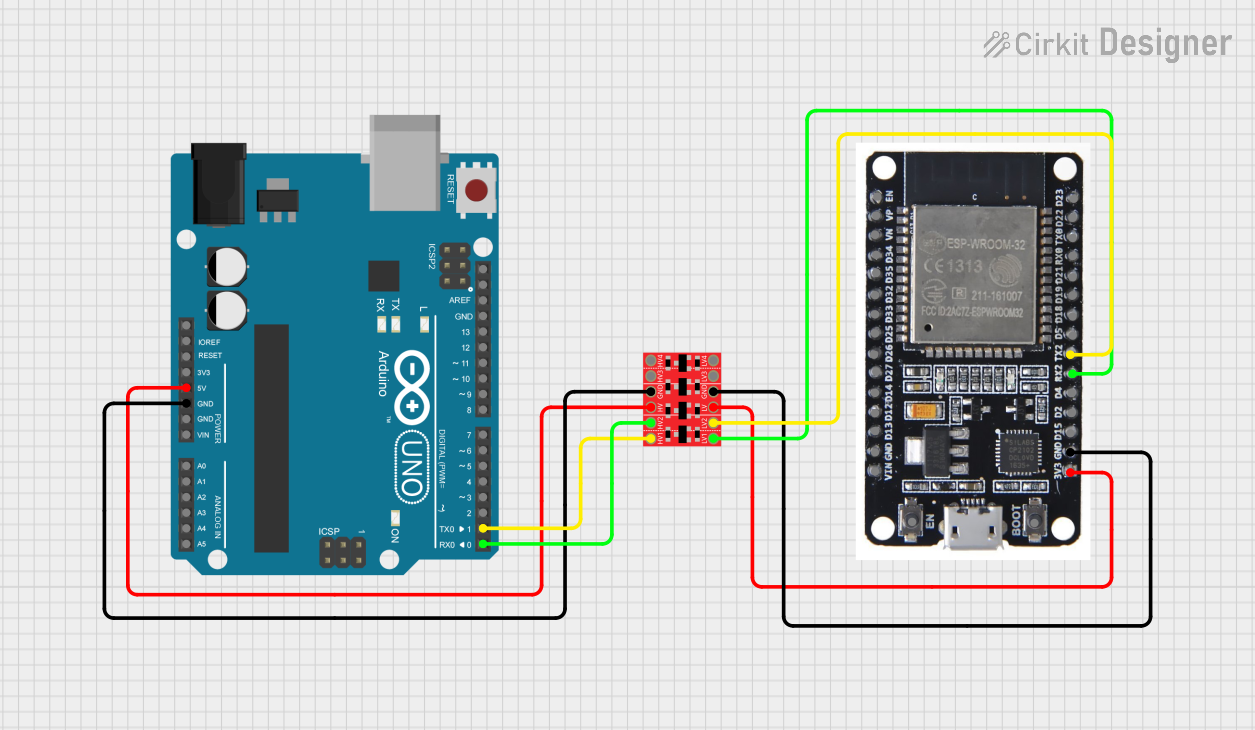
Example: Connecting to an Arduino UNO
Below is an example of using the Logic Level Converter to interface a 3.3V sensor with a 5V Arduino UNO via I2C:
Circuit Connections
- Connect the Arduino's
5Vpin to theHVpin of the converter. - Connect the Arduino's
GNDpin to theGNDpin of the converter. - Connect the sensor's
3.3Vpin to theLVpin of the converter. - Connect the sensor's
GNDpin to theGNDpin of the converter. - Connect the Arduino's
SCLandSDApins toTX1andTX2, respectively. - Connect the sensor's
SCLandSDApins toRX1andRX2, respectively.
Arduino Code Example
#include <Wire.h> // Include the Wire library for I2C communication

void setup() {
  Wire.begin(); // Initialize I2C communication
  Serial.begin(9600); // Start serial communication for debugging
  Serial.println("I2C Communication Initialized");
}

void loop() {
  Wire.beginTransmission(0x40); // Start communication with the sensor at address 0x40
  Wire.write(0x00); // Send a command or register address to the sensor
  Wire.endTransmission(); // End the transmission

  Wire.requestFrom(0x40, 2); // Request 2 bytes of data from the sensor
  if (Wire.available() == 2) { // Check if 2 bytes are available
    int data = Wire.read() << 8 | Wire.read(); // Read and combine the 2 bytes
    Serial.print("Sensor Data: ");
    Serial.println(data); // Print the sensor data
  }

  delay(1000); // Wait for 1 second before the next reading
}
Troubleshooting and FAQs
Common Issues and Solutions
No Communication Between Devices:
- Verify that the
HVandLVpins are connected to the correct voltage levels. - Ensure the
GNDpin is connected to the common ground of both devices. - Check for loose or incorrect wiring.
- Verify that the
Data Corruption or Noise:
- Use shorter wires to reduce noise and signal degradation.
- Add pull-up resistors for I2C communication if not already present.
One Side Not Responding:
- Confirm that the devices on both sides are powered and operational.
- Double-check the connections to the
TXandRXpins.
FAQs
Q1: Can I use this converter for analog signals?
A1: No, the Logic Level Converter is designed for digital signals only. It cannot be used for analog signal conversion.
Q2: What is the maximum data rate supported?
A2: The maximum data rate depends on the protocol and voltage levels. For I2C, it typically supports up to 100 kHz, but it may handle higher speeds for GPIO.
Q3: Do I need external pull-up resistors for I2C?
A3: Yes, external pull-up resistors are required for proper I2C communication. Use appropriate resistor values for the voltage levels in your circuit.
Q4: Can I use fewer than 8 channels?
A4: Yes, you can use as many or as few channels as needed. Unused channels can be left unconnected.