How to Use SPARK MAX Motor Controller: Examples, Pinouts, and Specs
Introduction
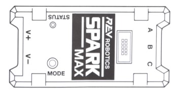
The SPARK MAX Motor Controller (Part ID: REV-11-2158) is a versatile and advanced motor controller designed by REV Robotics for use in robotics, particularly in the FIRST Robotics Competition. It is capable of controlling brushless and brushed DC motors, offering high performance and a wide range of features. Common applications include driving wheels, arms, lifts, and other robotic mechanisms.
Explore Projects Built with SPARK MAX Motor Controller
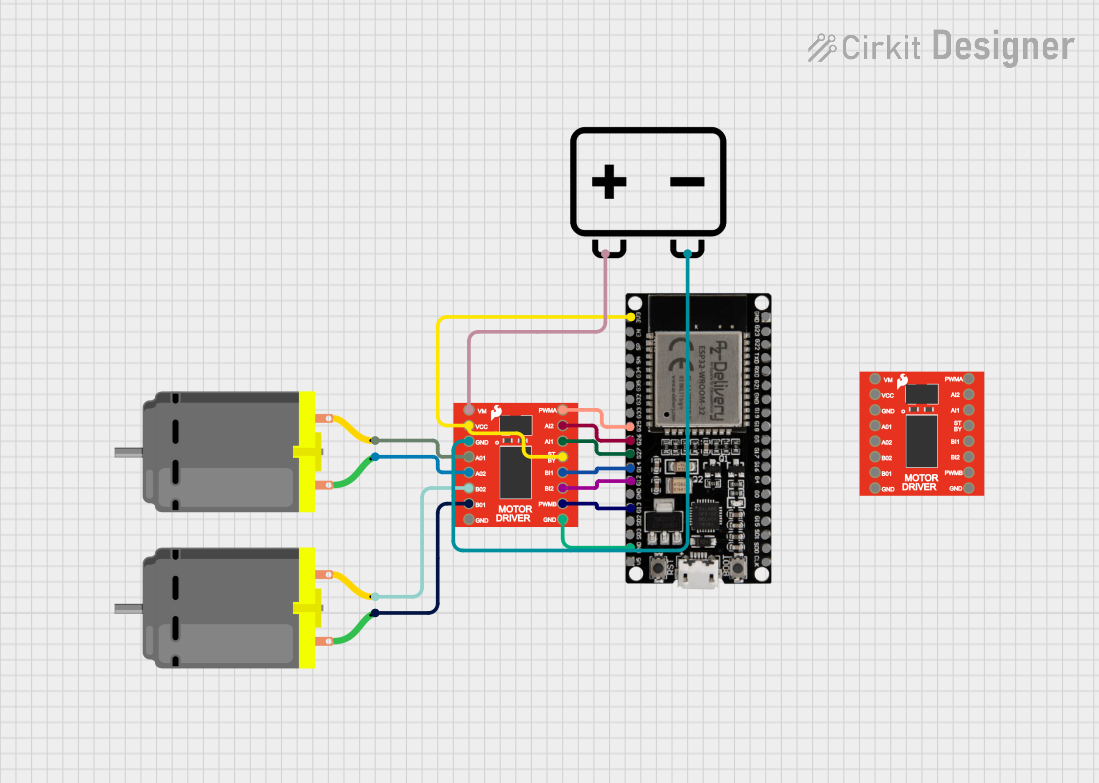
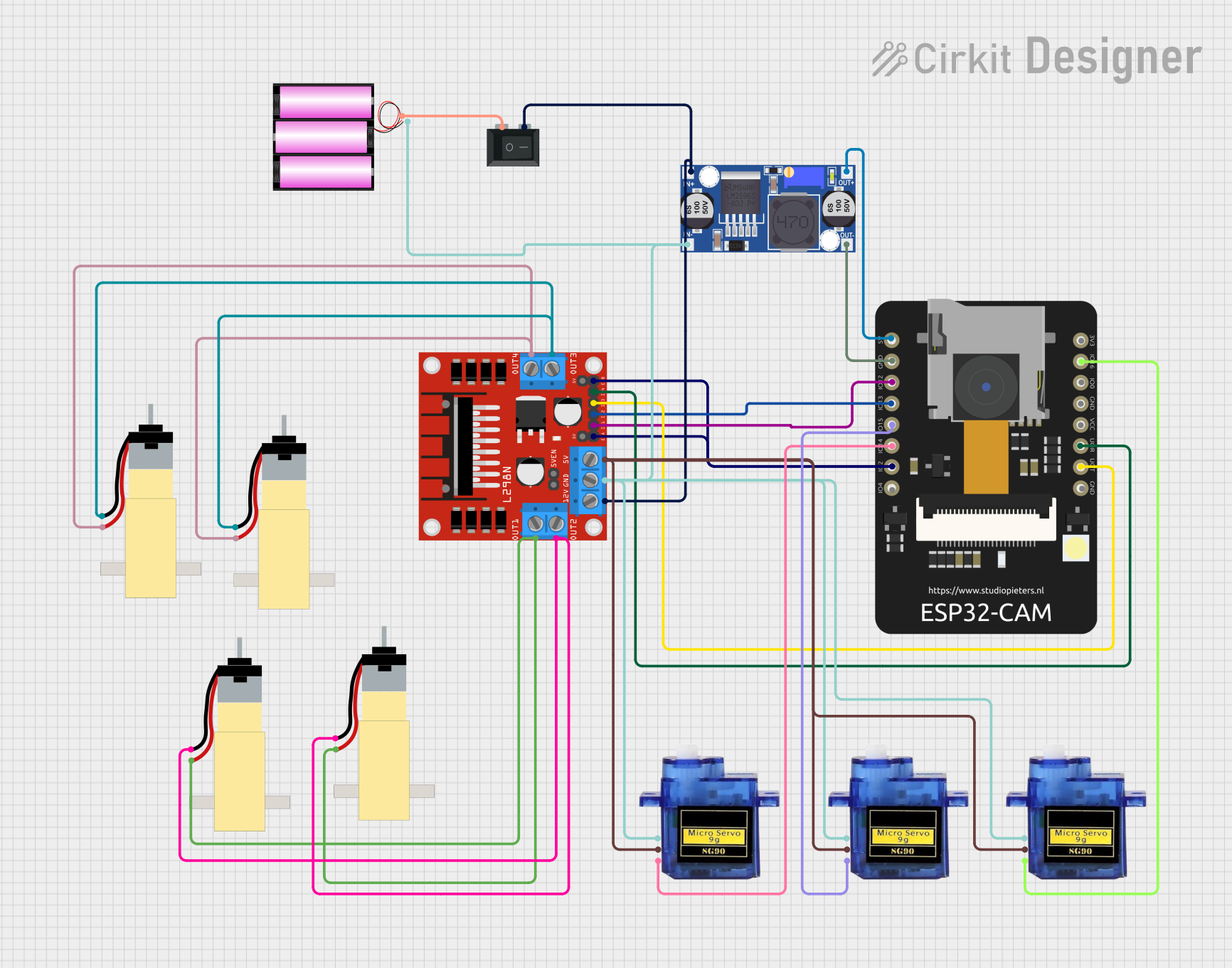
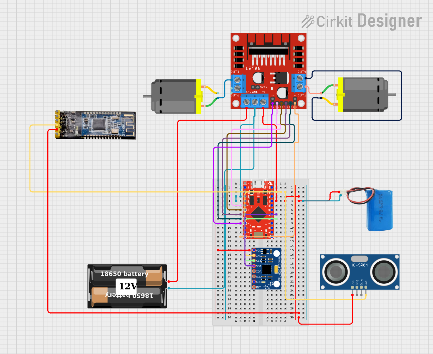

Explore Projects Built with SPARK MAX Motor Controller
Technical Specifications
Key Technical Details
- Motor Types Supported: Brushless DC (BLDC), Brushed DC
- Input Voltage: 6V - 24V
- Continuous Current: 60A
- Peak Current: 100A (for a few seconds)
- PWM Input Pulse Width: 1ms - 2ms
- USB-C Port: For firmware updates and configuration
- Data Port: CAN, I2C, UART, SPI for sensor input and telemetry
- Dimensions: 2.45 in. x 1.45 in. x 0.98 in.
- Weight: 0.2 lbs
Pin Configuration and Descriptions
| Pin Number | Description | Notes |
|---|---|---|
| 1 | PWM Signal | Standard servo-style PWM input |
| 2 | Forward Limit Switch (FWD) | Digital input, active low |
| 3 | Reverse Limit Switch (REV) | Digital input, active low |
| 4 | Quadrature Encoder A (ENC A) | Encoder input A |
| 5 | Quadrature Encoder B (ENC B) | Encoder input B |
| 6 | Analog Sensor (ANA) | Analog sensor input |
| 7 | Data Port (DATA) | CAN, I2C, UART, SPI |
| 8 | Power Input (+V) | Positive voltage supply |
| 9 | Power Input (GND) | Ground |
Usage Instructions
How to Use the Component in a Circuit
Power Connections:
- Connect the positive voltage supply to Pin 8 (+V) and ground to Pin 9 (GND).
- Ensure the power supply voltage is within the specified range (6V - 24V).
Motor Connections:
- Connect the motor leads to the motor output terminals on the SPARK MAX.
- For brushless motors, ensure the correct phase alignment.
Signal Connections:
- Connect the PWM signal to Pin 1 for standard PWM control.
- Optionally, connect limit switches to Pins 2 (FWD) and 3 (REV) for hardware limit switch functionality.
Encoder and Sensor Connections:
- If using an encoder, connect the encoder channels to Pins 4 (ENC A) and 5 (ENC B).
- For analog sensors, connect the output to Pin 6 (ANA).
Data Port Usage:
- Utilize the Data Port (Pin 7) for advanced features such as CAN communication or sensor input.
Important Considerations and Best Practices
- Always ensure that the power supply is disconnected before making any connections to the SPARK MAX.
- Use appropriate wire gauges to handle the expected current draw.
- Configure the SPARK MAX using the REV Hardware Client before use to set the appropriate motor type and control mode.
- Update the firmware to the latest version for optimal performance and feature access.
- When using PWM control, ensure that the signal is within the specified pulse width range.
- For CAN communication, ensure proper termination of the CAN bus.
Troubleshooting and FAQs
Common Issues
- Motor not responding: Check connections, ensure proper motor type configuration, and verify that the input signal is within the correct range.
- Overcurrent or thermal shutdown: Reduce the load on the motor or improve cooling to the SPARK MAX.
- Communication errors: Verify wiring for CAN or other communication methods and check for correct termination.
Solutions and Tips
- LED Status: Refer to the SPARK MAX User Manual for LED status indicators to diagnose issues.
- Firmware Updates: Regularly update the firmware using the REV Hardware Client.
- Wiring Checks: Perform regular inspections of all connections for wear and secure attachment.
FAQs
Q: Can the SPARK MAX be used with any brushless motor?
- A: It is designed to work with a wide range of brushless motors, but always check compatibility.
Q: How do I update the firmware?
- A: Use the USB-C port to connect to a computer and use the REV Hardware Client for updates.
Q: What is the maximum wire size that can be used for power connections?
- A: The power terminals can accommodate up to 12 AWG wire.
Example Code for Arduino UNO
#include <Servo.h>

Servo sparkMax;

void setup() {
  // Attach the SPARK MAX Motor Controller to pin 9
  sparkMax.attach(9);
}

void loop() {
  // Set the motor speed to half throttle (0 is full reverse, 180 is full forward)
  sparkMax.write(90); // Neutral position
  delay(1000); // Wait for 1 second

  // Full forward
  sparkMax.write(180);
  delay(1000); // Wait for 1 second

  // Full reverse
  sparkMax.write(0);
  delay(1000); // Wait for 1 second
}
Note: The above example assumes the SPARK MAX is in PWM control mode and connected to an Arduino UNO on pin 9. Adjust the pin number and control logic as necessary for your specific setup.