Cirkit Designer Logo
Cirkit Designer
Your all-in-one circuit design IDE
Home / 
Component Documentation

How to Use D: Examples, Pinouts, and Specs

Image of D
Cirkit Designer LogoDesign with D in Cirkit Designer

Introduction

A diode is a semiconductor device that allows current to flow in one direction only, known as the forward direction, while blocking current in the reverse direction. This unidirectional behavior is called rectification and is used in a variety of applications such as power conversion, signal demodulation, and as protection circuits.

Explore Projects Built with D

Use Cirkit Designer to design, explore, and prototype these projects online. Some projects support real-time simulation. Click "Open Project" to start designing instantly!
Arduino UNO Controlled Touch-Activated LED and Buzzer System
Image of touch sensor controlled led: A project utilizing D in a practical application
This circuit features an Arduino UNO microcontroller connected to a touch sensor, a red LED with a series resistor, and a buzzer. The touch sensor's output is connected to digital pin D2 of the Arduino, which likely controls the LED connected to pin D13 and the buzzer connected to pin D5 based on touch input. The LED's anode is directly connected to the Arduino, while its cathode is connected through a 220-ohm resistor, and the buzzer's other pin is grounded, suggesting that both are controlled via digital output pins for signaling or user interaction.
Cirkit Designer LogoOpen Project in Cirkit Designer
Arduino-Based Smart Environmental Control System with Temperature Sensing and Relay Actuation
Image of Proyectos 903: A project utilizing D in a practical application
This circuit features multiple Arduino 101 microcontrollers used to read temperature and humidity data from DHT22 and DHT11 sensors, control a mini water pump and a DC motor via relay modules, and operate a traffic light. The system is powered by 9V batteries, with the relays serving to switch power to the motor and pump based on sensor inputs or other conditions. The traffic light is directly driven by one of the Arduinos, which manages the signaling.
Cirkit Designer LogoOpen Project in Cirkit Designer
Arduino UNO-based Pushbutton Music Keyboard
Image of rerey project: A project utilizing D in a practical application
This circuit is designed as a simple electronic music keyboard using an Arduino UNO microcontroller. Six pushbuttons are connected to digital inputs D2 to D7, each representing a different musical note when pressed. A speaker is connected to digital output D8 through a resistor, and the Arduino is programmed to generate different tones corresponding to the buttons pressed, effectively creating a basic piano keyboard.
Cirkit Designer LogoOpen Project in Cirkit Designer
Arduino UNO Controlled Traffic Light with Joystick Interface
Image of traffic light: A project utilizing D in a practical application
This circuit features an Arduino UNO microcontroller interfaced with a joystick module and a traffic light module. The joystick's vertical and horizontal movements are read by the Arduino through analog inputs A0 and A1, while the joystick's switch is connected to digital pin D7. The traffic light's green, yellow, and red LEDs are controlled by digital pins D3, D2, and D1 respectively, and all modules share a common ground with the Arduino.
Cirkit Designer LogoOpen Project in Cirkit Designer

Explore Projects Built with D

Use Cirkit Designer to design, explore, and prototype these projects online. Some projects support real-time simulation. Click "Open Project" to start designing instantly!
Image of touch sensor controlled led: A project utilizing D in a practical application
Arduino UNO Controlled Touch-Activated LED and Buzzer System
This circuit features an Arduino UNO microcontroller connected to a touch sensor, a red LED with a series resistor, and a buzzer. The touch sensor's output is connected to digital pin D2 of the Arduino, which likely controls the LED connected to pin D13 and the buzzer connected to pin D5 based on touch input. The LED's anode is directly connected to the Arduino, while its cathode is connected through a 220-ohm resistor, and the buzzer's other pin is grounded, suggesting that both are controlled via digital output pins for signaling or user interaction.
Cirkit Designer LogoOpen Project in Cirkit Designer
Image of Proyectos 903: A project utilizing D in a practical application
Arduino-Based Smart Environmental Control System with Temperature Sensing and Relay Actuation
This circuit features multiple Arduino 101 microcontrollers used to read temperature and humidity data from DHT22 and DHT11 sensors, control a mini water pump and a DC motor via relay modules, and operate a traffic light. The system is powered by 9V batteries, with the relays serving to switch power to the motor and pump based on sensor inputs or other conditions. The traffic light is directly driven by one of the Arduinos, which manages the signaling.
Cirkit Designer LogoOpen Project in Cirkit Designer
Image of rerey project: A project utilizing D in a practical application
Arduino UNO-based Pushbutton Music Keyboard
This circuit is designed as a simple electronic music keyboard using an Arduino UNO microcontroller. Six pushbuttons are connected to digital inputs D2 to D7, each representing a different musical note when pressed. A speaker is connected to digital output D8 through a resistor, and the Arduino is programmed to generate different tones corresponding to the buttons pressed, effectively creating a basic piano keyboard.
Cirkit Designer LogoOpen Project in Cirkit Designer
Image of traffic light: A project utilizing D in a practical application
Arduino UNO Controlled Traffic Light with Joystick Interface
This circuit features an Arduino UNO microcontroller interfaced with a joystick module and a traffic light module. The joystick's vertical and horizontal movements are read by the Arduino through analog inputs A0 and A1, while the joystick's switch is connected to digital pin D7. The traffic light's green, yellow, and red LEDs are controlled by digital pins D3, D2, and D1 respectively, and all modules share a common ground with the Arduino.
Cirkit Designer LogoOpen Project in Cirkit Designer

Common Applications and Use Cases

  • Power Supply Rectification: Converts alternating current (AC) to direct current (DC).
  • Signal Demodulation: Extracts information from modulated signals.
  • Overvoltage Protection: Protects circuits from voltage spikes.
  • Logic Gates: Forms the basic building blocks of digital circuits.
  • Voltage Clamping: Limits the voltage to a certain level.

Technical Specifications

Key Technical Details

  • Maximum Forward Current (IF): The maximum current the diode can conduct in the forward direction.
  • Peak Inverse Voltage (PIV): The maximum voltage the diode can withstand in the reverse direction without breakdown.
  • Forward Voltage Drop (VF): The voltage drop across the diode when it is conducting.
  • Reverse Current (IR): The small leakage current that flows when the diode is reverse-biased.
  • Junction Temperature (TJ): The maximum operating temperature of the diode's semiconductor junction.

Pin Configuration and Descriptions

Pin Number Name Description
1 Anode The terminal where current enters when forward-biased.
2 Cathode The terminal where current exits when forward-biased.

Usage Instructions

How to Use the Diode in a Circuit

  1. Identify the Anode and Cathode: The anode is typically marked with a plus sign, and the cathode is marked with a band or minus sign.
  2. Forward Bias Connection: Connect the anode to the positive side of the power source and the cathode to the negative side to allow current flow.
  3. Reverse Bias Connection: Reverse the connections to block current flow.

Important Considerations and Best Practices

  • Current Rating: Ensure the diode's current rating exceeds the circuit's maximum current.
  • Voltage Rating: The diode's PIV should be higher than the maximum reverse voltage expected.
  • Heat Dissipation: Use a heat sink if the power dissipation is high to prevent overheating.
  • Reverse Recovery Time: For high-frequency applications, choose a diode with a low reverse recovery time.

Troubleshooting and FAQs

Common Issues

  • Diode Not Conducting: Ensure the diode is forward-biased and that the anode is connected to the positive voltage.
  • Diode Burnt Out: Check if the diode was subjected to a current or voltage higher than its ratings.
  • Unexpected Voltage Drops: Verify that the forward voltage drop is within the expected range for the diode.

Solutions and Tips for Troubleshooting

  • Testing Diode Functionality: Use a multimeter in diode mode to check for proper forward and reverse bias operation.
  • Replacing a Faulty Diode: If the diode is defective, replace it with one that has the same or higher ratings.
  • Circuit Analysis: Review the entire circuit to ensure that the diode is not being stressed by other components.

FAQs

Q: Can I use any diode for rectification? A: No, you must choose a diode with the appropriate current and voltage ratings for your application.

Q: Why is my diode getting hot? A: It could be due to excessive current flow or insufficient heat sinking.

Q: How do I know if a diode is working? A: A multimeter in diode mode should show low resistance in one direction (forward-biased) and high resistance in the other (reverse-biased).

Example Code for Arduino UNO

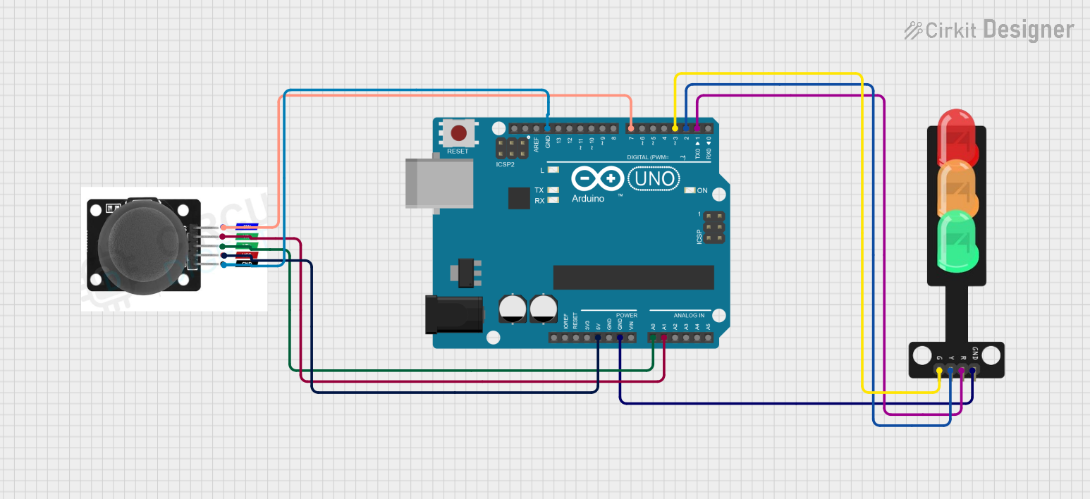
If you're using a diode in conjunction with an Arduino UNO, for example, to protect the inputs from negative voltage spikes, here's a simple code snippet that demonstrates reading an analog input with diode protection.

// Define the analog input pin
int analogInputPin = A0; 
// Variable to store the analog input value
int sensorValue = 0;      

void setup() {
  // Start the serial communication
  Serial.begin(9600);      
}

void loop() {
  // Read the analog input value (0 to 1023)
  sensorValue = analogRead(analogInputPin); 
  // Convert the analog reading to voltage (0 to 5V)
  float voltage = sensorValue * (5.0 / 1023.0); 
  // Print the voltage to the Serial Monitor
  Serial.println(voltage);                   
  // Wait for 100 milliseconds before the next loop
  delay(100);                               
}

Remember to connect the diode in series with the signal line, with the anode facing the signal source and the cathode facing the Arduino input pin. This will ensure that any negative voltage is blocked, protecting the Arduino from damage.