
How to Use MMA7260: Examples, Pinouts, and Specs
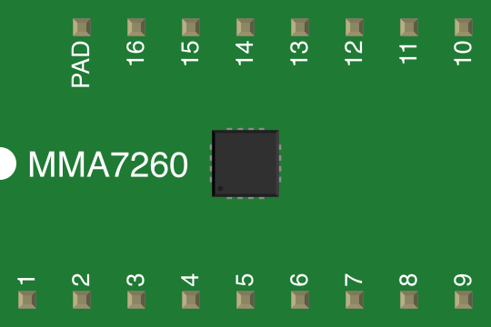
 Design with MMA7260 in Cirkit Designer
Introduction
The MMA7260Q is a three-axis accelerometer manufactured by Freescale Semiconductor. It is designed to measure acceleration along the X, Y, and Z axes, making it ideal for motion sensing applications. The device outputs an analog voltage proportional to the acceleration experienced by each axis. With its compact size and low power consumption, the MMA7260 is widely used in applications such as tilt detection, free-fall detection, gesture recognition, and gaming controllers.
Explore Projects Built with MMA7260
 Open Project in Cirkit Designer
 Open Project in Cirkit Designer
 Open Project in Cirkit Designer
 Open Project in Cirkit Designer
Explore Projects Built with MMA7260
Open Project in Cirkit DesignerOpen Project in Cirkit DesignerOpen Project in Cirkit DesignerOpen Project in Cirkit DesignerCommon Applications:
- Tilt sensing in portable devices
- Free-fall detection for hard drive protection
- Gesture recognition in gaming and robotics
- Vibration monitoring and measurement
- Navigation systems and inertial measurement units (IMUs)
Technical Specifications
Key Technical Details:
| Parameter | Value |
|---|---|
| Supply Voltage (Vdd) | 2.2V to 3.6V |
| Output Voltage Range | 0V to Vdd |
| Sensitivity (Selectable) | 1.5g, 2g, 4g, 6g |
| Sensitivity (1.5g mode) | 800 mV/g |
| Sensitivity (2g mode) | 600 mV/g |
| Sensitivity (4g mode) | 300 mV/g |
| Sensitivity (6g mode) | 200 mV/g |
| Zero-g Output Voltage | ~1.65V (at Vdd = 3.3V) |
| Operating Temperature | -40°C to +85°C |
| Current Consumption | 500 µA (typical) |
| Sleep Mode Current | 3 µA (typical) |
| Package Type | QFN-16 (4mm x 4mm) |
Pin Configuration and Descriptions:
The MMA7260Q comes in a 16-pin QFN package. Below is the pinout and description:
| Pin Number | Pin Name | Description |
|---|---|---|
| 1 | Vdd | Power supply input (2.2V to 3.6V) |
| 2 | GND | Ground |
| 3 | XOUT | Analog output voltage for X-axis acceleration |
| 4 | YOUT | Analog output voltage for Y-axis acceleration |
| 5 | ZOUT | Analog output voltage for Z-axis acceleration |
| 6 | G-Select1 | Sensitivity selection input (bit 1) |
| 7 | G-Select2 | Sensitivity selection input (bit 2) |
| 8 | Sleep | Sleep mode control input |
| 9-16 | NC | No connection |
Usage Instructions
How to Use the MMA7260 in a Circuit:
- Power Supply: Connect the Vdd pin to a regulated 3.3V power supply and the GND pin to ground.
- Output Connections: Connect the XOUT, YOUT, and ZOUT pins to an ADC (Analog-to-Digital Converter) or microcontroller analog input pins to read the acceleration data.
- Sensitivity Selection: Use the G-Select1 and G-Select2 pins to configure the sensitivity mode:
- G-Select1 = 0, G-Select2 = 0 → 1.5g mode
- G-Select1 = 1, G-Select2 = 0 → 2g mode
- G-Select1 = 0, G-Select2 = 1 → 4g mode
- G-Select1 = 1, G-Select2 = 1 → 6g mode
- Sleep Mode: To reduce power consumption, drive the Sleep pin HIGH to enable sleep mode. Drive it LOW to resume normal operation.
Important Considerations:
- Use decoupling capacitors (e.g., 0.1 µF) close to the Vdd pin to reduce noise.
- Ensure the analog output pins (XOUT, YOUT, ZOUT) are connected to high-impedance inputs to avoid loading effects.
- Mount the accelerometer on a stable PCB to minimize mechanical vibrations and noise.
- Calibrate the zero-g output voltage for each axis to account for any offset errors.
Example: Connecting MMA7260 to Arduino UNO
Below is an example of how to interface the MMA7260 with an Arduino UNO to read acceleration data:
Circuit Connections:
- Vdd → 3.3V pin on Arduino
- GND → GND pin on Arduino
- XOUT → A0 (Analog Pin 0)
- YOUT → A1 (Analog Pin 1)
- ZOUT → A2 (Analog Pin 2)
- G-Select1 → GND (1.5g mode)
- G-Select2 → GND (1.5g mode)
- Sleep → GND (Normal operation)
Arduino Code:
// MMA7260Q Accelerometer Example Code
// Reads acceleration data from X, Y, and Z axes and prints to Serial Monitor

const int xPin = A0; // X-axis output connected to Analog Pin 0
const int yPin = A1; // Y-axis output connected to Analog Pin 1
const int zPin = A2; // Z-axis output connected to Analog Pin 2

void setup() {
  Serial.begin(9600); // Initialize serial communication at 9600 baud
}

void loop() {
  // Read analog values from the accelerometer
  int xValue = analogRead(xPin);
  int yValue = analogRead(yPin);
  int zValue = analogRead(zPin);

  // Convert analog values to voltage (assuming 3.3V reference)
  float xVoltage = xValue * (3.3 / 1023.0);
  float yVoltage = yValue * (3.3 / 1023.0);
  float zVoltage = zValue * (3.3 / 1023.0);

  // Print the voltage values to the Serial Monitor
  Serial.print("X Voltage: ");
  Serial.print(xVoltage);
  Serial.print(" V, Y Voltage: ");
  Serial.print(yVoltage);
  Serial.print(" V, Z Voltage: ");
  Serial.print(zVoltage);
  Serial.println(" V");

  delay(500); // Wait for 500ms before the next reading
}
Troubleshooting and FAQs
Common Issues:
No Output Voltage from XOUT, YOUT, or ZOUT:
- Ensure the Vdd and GND pins are properly connected.
- Verify that the Sleep pin is LOW (normal operation mode).
Incorrect or Noisy Readings:
- Check for proper decoupling capacitors near the Vdd pin.
- Ensure the accelerometer is mounted securely to avoid mechanical vibrations.
- Verify that the ADC reference voltage matches the MMA7260's output range.
Sensitivity Not Changing:
- Confirm the G-Select1 and G-Select2 pins are correctly configured.
- Check for loose or incorrect connections to these pins.
FAQs:
Q1: Can the MMA7260 operate at 5V?
No, the MMA7260 operates within a supply voltage range of 2.2V to 3.6V. Exceeding this range may damage the device.
Q2: How do I calibrate the accelerometer?
To calibrate, measure the zero-g output voltage for each axis when the device is stationary and level. Subtract this offset from subsequent readings.
Q3: What is the maximum measurable acceleration?
The maximum measurable acceleration depends on the selected sensitivity mode:
- 1.5g mode: ±1.5g
- 2g mode: ±2g
- 4g mode: ±4g
- 6g mode: ±6g
Q4: Can I use the MMA7260 for vibration analysis?
Yes, the MMA7260 can measure vibrations, but ensure proper mounting and filtering to minimize noise.
This concludes the documentation for the MMA7260Q accelerometer.