
How to Use data logger: Examples, Pinouts, and Specs
 Design with data logger in Cirkit Designer
Introduction
A data logger is an electronic device designed to record data over time. It is commonly used for monitoring environmental conditions such as temperature, humidity, pressure, and other parameters. Data loggers are equipped with sensors to collect data and can either store the data internally or transmit it to a computer or cloud-based system for further analysis. These devices are widely used in industries such as agriculture, environmental science, logistics, and manufacturing.
Explore Projects Built with data logger
 Open Project in Cirkit Designer
 Open Project in Cirkit Designer
 Open Project in Cirkit Designer
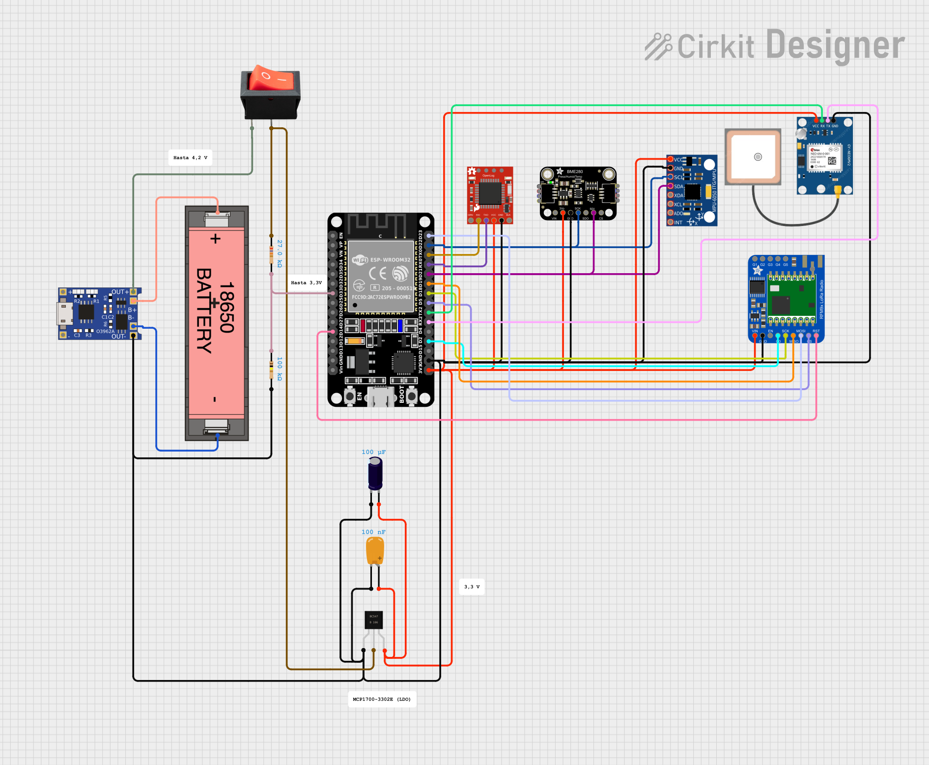 Open Project in Cirkit Designer
Explore Projects Built with data logger
Open Project in Cirkit DesignerOpen Project in Cirkit DesignerOpen Project in Cirkit DesignerOpen Project in Cirkit DesignerCommon Applications and Use Cases
- Monitoring temperature and humidity in greenhouses or storage facilities.
- Tracking environmental conditions during transportation of sensitive goods.
- Recording pressure and temperature in industrial processes.
- Collecting data for scientific research and experiments.
- Monitoring energy usage in smart homes or industrial setups.
Technical Specifications
Below are the general technical specifications for a typical data logger. Note that specific models may vary in their capabilities.
Key Technical Details
- Power Supply: 3.3V to 5V DC (depending on the model)
- Data Storage: Internal memory (e.g., EEPROM or SD card) or external storage
- Communication Interfaces: UART, I2C, SPI, or USB
- Sampling Rate: Adjustable (e.g., 1 sample per second to 1 sample per hour)
- Sensor Compatibility: Supports temperature, humidity, pressure, and other sensors
- Operating Temperature: -40°C to 85°C (varies by model)
- Data Format: CSV, JSON, or proprietary formats
Pin Configuration and Descriptions
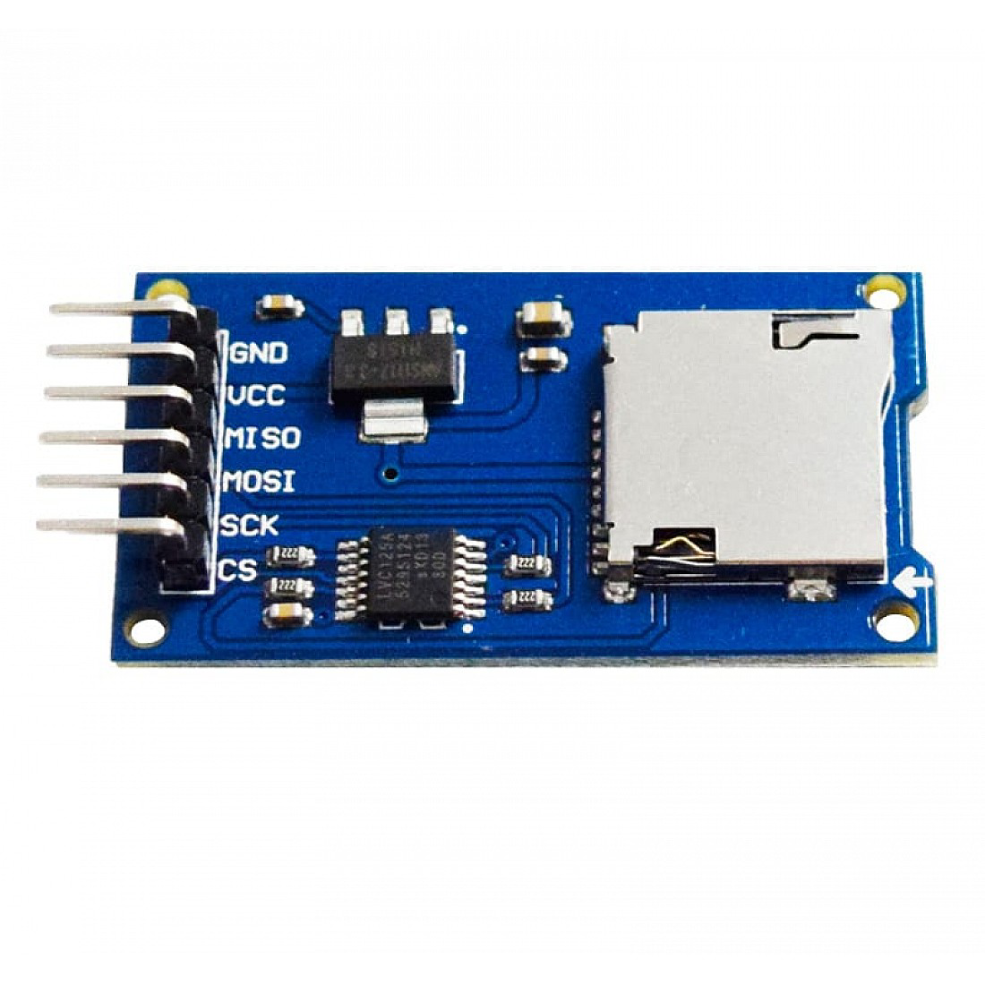
The pin configuration for a typical data logger module is as follows:
| Pin Name | Description |
|---|---|
| VCC | Power input (3.3V or 5V, depending on the module). |
| GND | Ground connection. |
| SDA | Serial Data Line for I2C communication. |
| SCL | Serial Clock Line for I2C communication. |
| TX | Transmit pin for UART communication. |
| RX | Receive pin for UART communication. |
| CS | Chip Select pin for SPI communication (used with SD card modules). |
| MOSI | Master Out Slave In pin for SPI communication. |
| MISO | Master In Slave Out pin for SPI communication. |
| SCK | Serial Clock pin for SPI communication. |
Usage Instructions
How to Use the Component in a Circuit
- Power the Data Logger: Connect the VCC pin to a 3.3V or 5V power source (as specified by the module) and the GND pin to the ground.
- Connect Sensors: Attach compatible sensors (e.g., temperature, humidity) to the appropriate input pins.
- Choose Communication Protocol: Depending on your setup, connect the data logger to a microcontroller or computer using I2C, UART, or SPI.
- Configure the Logger: Use the manufacturer's software or write custom code to configure the sampling rate, data storage format, and other parameters.
- Start Logging: Begin data collection by powering on the device and initiating the logging process.
Important Considerations and Best Practices
- Power Supply: Ensure the power supply voltage matches the module's requirements to avoid damage.
- Sensor Placement: Place sensors in appropriate locations to ensure accurate readings.
- Data Backup: Regularly transfer data from the logger to a computer or cloud storage to prevent data loss.
- Environmental Protection: If used outdoors, protect the data logger and sensors from moisture and extreme conditions.
- Firmware Updates: Check for firmware updates from the manufacturer to improve performance and compatibility.
Example: Using a Data Logger with Arduino UNO
Below is an example of how to use a data logger with an SD card module to record temperature data from a DHT11 sensor.
Required Components
- Arduino UNO
- Data logger module with SD card support
- DHT11 temperature and humidity sensor
- SD card
- Connecting wires
Circuit Diagram
- Connect the VCC and GND pins of the data logger and DHT11 sensor to the Arduino's 5V and GND pins.
- Connect the SDA and SCL pins of the data logger to the Arduino's A4 and A5 pins, respectively.
- Connect the DHT11 data pin to Arduino digital pin 2.
Code Example
#include <SD.h>
#include <DHT.h>

#define DHTPIN 2       // Pin connected to the DHT11 sensor
#define DHTTYPE DHT11  // Define the type of DHT sensor
#define CSPIN 10       // Chip Select pin for the SD card module

DHT dht(DHTPIN, DHTTYPE);

void setup() {
  Serial.begin(9600);
  dht.begin();

  // Initialize SD card
  if (!SD.begin(CSPIN)) {
    Serial.println("SD card initialization failed!");
    return;
  }
  Serial.println("SD card initialized.");
}

void loop() {
  // Read temperature and humidity
  float temperature = dht.readTemperature();
  float humidity = dht.readHumidity();

  // Check if readings are valid
  if (isnan(temperature) || isnan(humidity)) {
    Serial.println("Failed to read from DHT sensor!");
    return;
  }

  // Open file on SD card
  File dataFile = SD.open("datalog.txt", FILE_WRITE);

  // If the file is available, write data to it
  if (dataFile) {
    dataFile.print("Temperature: ");
    dataFile.print(temperature);
    dataFile.print(" °C, Humidity: ");
    dataFile.print(humidity);
    dataFile.println(" %");
    dataFile.close(); // Close the file
    Serial.println("Data logged.");
  } else {
    Serial.println("Error opening datalog.txt");
  }

  delay(2000); // Wait 2 seconds before next reading
}
Troubleshooting and FAQs
Common Issues Users Might Face
SD Card Initialization Fails:
- Cause: Incorrect wiring or incompatible SD card.
- Solution: Check the connections and ensure the SD card is formatted as FAT32.
Sensor Readings Are NaN:
- Cause: Faulty sensor or incorrect wiring.
- Solution: Verify the sensor connections and replace the sensor if necessary.
Data Not Saved to SD Card:
- Cause: File not opened properly or SD card is full.
- Solution: Ensure the file is opened in write mode and check the available space on the SD card.
Inaccurate Sensor Readings:
- Cause: Poor sensor placement or environmental interference.
- Solution: Place the sensor in a stable environment away from heat sources or drafts.
Solutions and Tips for Troubleshooting
- Double-check all connections and ensure they match the circuit diagram.
- Use a multimeter to verify power supply voltage and continuity of connections.
- Test the data logger with a simple example code to isolate issues.
- Refer to the manufacturer's documentation for model-specific troubleshooting steps.