How to Use 1.14 TFT 135x240: Examples, Pinouts, and Specs
Introduction
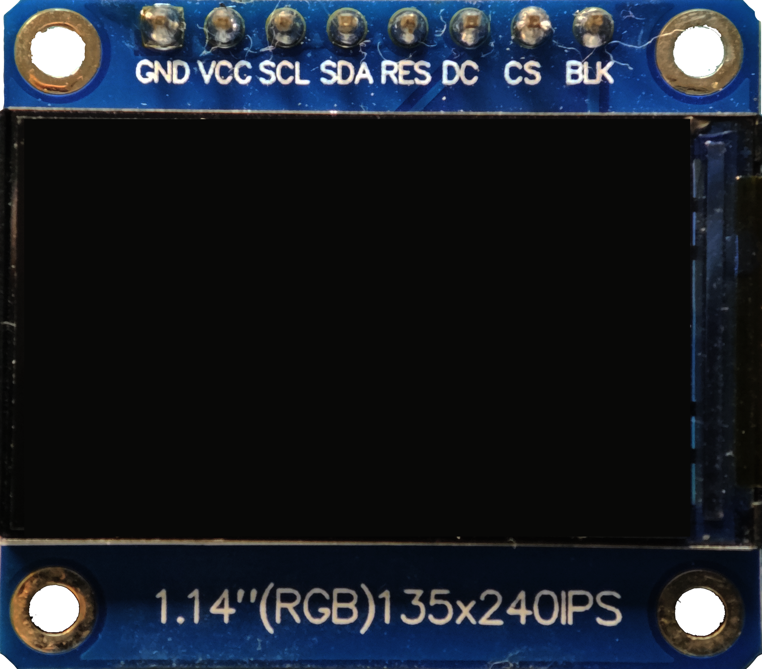
The 1.14-inch TFT 135x240 display, manufactured by TFT (Part ID: LCD 1.14 TFT 135x240), is a compact thin-film transistor (TFT) display module. It features a resolution of 135x240 pixels, making it ideal for small electronic devices requiring clear and vibrant graphical or textual output. This display is commonly used in applications such as wearable devices, handheld instruments, IoT projects, and small embedded systems.
Its compact size, high resolution, and compatibility with popular microcontrollers like the Arduino UNO make it a versatile choice for hobbyists and professionals alike.
Explore Projects Built with 1.14 TFT 135x240


Explore Projects Built with 1.14 TFT 135x240
Technical Specifications
Below are the key technical details of the 1.14 TFT 135x240 display:
| Parameter | Specification |
|---|---|
| Display Type | TFT (Thin-Film Transistor) |
| Screen Size | 1.14 inches |
| Resolution | 135x240 pixels |
| Interface | SPI (Serial Peripheral Interface) |
| Operating Voltage | 3.3V (logic level) |
| Backlight Voltage | 3.0V to 3.3V |
| Current Consumption | ~20mA (typical, with backlight on) |
| Driver IC | ST7789 |
| Viewing Angle | 160° |
| Color Depth | 262K colors (18-bit RGB) |
| Operating Temperature | -20°C to 70°C |
Pin Configuration
The 1.14 TFT 135x240 display module typically has the following pinout:
| Pin Name | Pin Number | Description |
|---|---|---|
| GND | 1 | Ground connection |
| VCC | 2 | Power supply (3.3V) |
| SCL | 3 | Serial Clock (SPI clock input) |
| SDA | 4 | Serial Data (SPI data input) |
| RES | 5 | Reset pin (active low) |
| DC | 6 | Data/Command control pin |
| BLK | 7 | Backlight control (connect to 3.3V for always on) |
Usage Instructions
Connecting the Display to an Arduino UNO
The 1.14 TFT 135x240 display uses the SPI interface, which is supported by the Arduino UNO. Below is a typical wiring guide:
| Display Pin | Arduino UNO Pin |
|---|---|
| GND | GND |
| VCC | 3.3V |
| SCL | D13 (SCK) |
| SDA | D11 (MOSI) |
| RES | D8 |
| DC | D9 |
| BLK | 3.3V |
Arduino Code Example
The following example demonstrates how to initialize and display basic graphics on the 1.14 TFT 135x240 using the Arduino IDE. This example uses the Adafruit_GFX and Adafruit_ST7789 libraries, which must be installed via the Arduino Library Manager.
#include <Adafruit_GFX.h>      // Core graphics library
#include <Adafruit_ST7789.h>   // ST7789 driver library
#include <SPI.h>               // SPI library

// Define pins for the display
#define TFT_CS     10  // Chip select pin (not used, but required by library)
#define TFT_RST    8   // Reset pin
#define TFT_DC     9   // Data/Command pin

// Initialize the display object
Adafruit_ST7789 tft = Adafruit_ST7789(TFT_CS, TFT_DC, TFT_RST);

void setup() {
  // Initialize serial communication for debugging
  Serial.begin(9600);
  Serial.println("1.14 TFT 135x240 Display Test");

  // Initialize the display
  tft.init(135, 240);  // Initialize with width=135 and height=240
  tft.setRotation(1);  // Set display rotation (0-3)

  // Fill the screen with a solid color
  tft.fillScreen(ST77XX_BLACK);

  // Display some text
  tft.setTextColor(ST77XX_WHITE);
  tft.setTextSize(2);
  tft.setCursor(10, 10);
  tft.println("Hello, TFT!");

  // Draw a rectangle
  tft.drawRect(20, 50, 100, 50, ST77XX_RED);
}

void loop() {
  // Nothing to do here
}
Important Considerations
- Voltage Levels: The display operates at 3.3V logic levels. If using a 5V microcontroller (e.g., Arduino UNO), use level shifters to avoid damaging the display.
- Backlight Control: The backlight pin (BLK) can be connected to a PWM pin on the microcontroller for brightness control.
- Library Compatibility: Ensure you are using the latest versions of the Adafruit_GFX and Adafruit_ST7789 libraries for optimal performance.
Troubleshooting and FAQs
Common Issues
No Display Output:
- Verify all connections are secure and match the wiring table.
- Ensure the display is powered with 3.3V and not 5V.
- Check that the correct pins are defined in the code.
Flickering or Distorted Graphics:
- Ensure the SPI clock speed is not too high. Reduce the speed in the library settings if necessary.
- Verify that the backlight pin (BLK) is properly connected.
Library Errors:
- Ensure the Adafruit_GFX and Adafruit_ST7789 libraries are installed and up to date.
- Confirm that the correct display dimensions (135x240) are passed to the
tft.init()function.
FAQs
Q: Can I use this display with a 5V microcontroller?
A: Yes, but you must use level shifters to convert the 5V logic signals to 3.3V to avoid damaging the display.
Q: How do I control the backlight brightness?
A: Connect the BLK pin to a PWM-capable pin on your microcontroller and use analogWrite() to adjust brightness.
Q: Can I use this display with other microcontrollers like ESP32 or Raspberry Pi?
A: Yes, the display is compatible with any microcontroller that supports SPI communication. Adjust the wiring and code accordingly.
Q: What is the maximum SPI clock speed supported by the display?
A: The ST7789 driver typically supports SPI clock speeds up to 15-20 MHz. Check the datasheet for exact details.