
How to Use Adafruit Feedback Servo (small): Examples, Pinouts, and Specs
 Design with Adafruit Feedback Servo (small) in Cirkit Designer
Introduction
The Adafruit Feedback Servo (Small) is a compact servo motor with built-in feedback capabilities, enabling precise control of position and speed. Unlike standard servos, this component provides real-time feedback on its position, making it ideal for applications requiring high accuracy and closed-loop control. It is particularly suited for robotics, automation, and projects where precise movement and monitoring are essential.
Explore Projects Built with Adafruit Feedback Servo (small)
 Open Project in Cirkit Designer
 Open Project in Cirkit Designer
 Open Project in Cirkit Designer
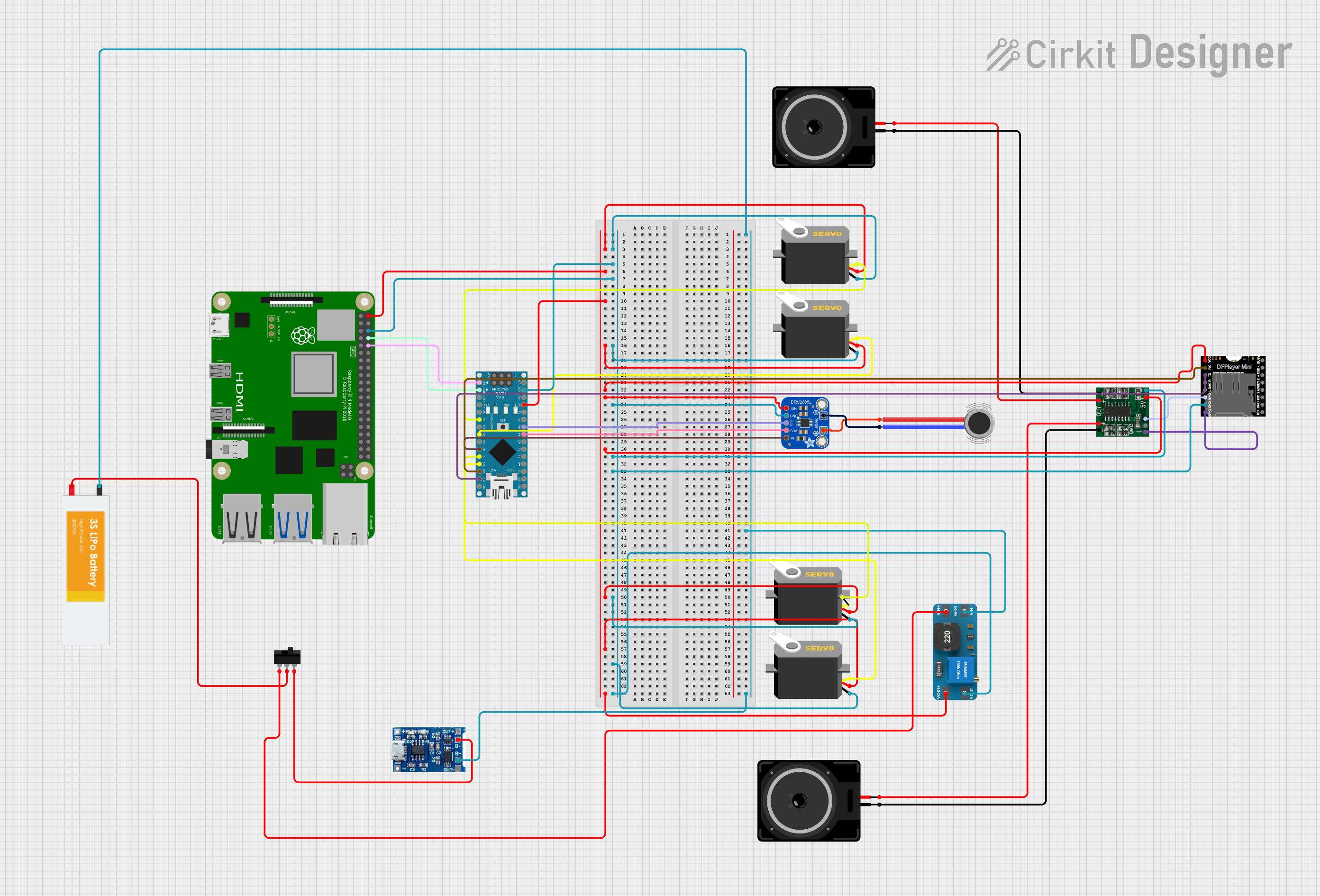 Open Project in Cirkit Designer
Explore Projects Built with Adafruit Feedback Servo (small)
Open Project in Cirkit DesignerOpen Project in Cirkit DesignerOpen Project in Cirkit DesignerOpen Project in Cirkit DesignerCommon Applications
- Robotics (e.g., robotic arms, grippers)
- Automation systems
- Pan-tilt camera mounts
- Educational projects involving servo control
- Closed-loop control systems
Technical Specifications
The Adafruit Feedback Servo (Small) is designed to deliver reliable performance in a compact form factor. Below are its key technical details:
General Specifications
| Parameter | Value |
|---|---|
| Operating Voltage | 4.8V to 6.0V |
| Stall Torque | 1.6 kg·cm @ 4.8V, 1.8 kg·cm @ 6.0V |
| Operating Speed | 0.12 sec/60° @ 4.8V, 0.10 sec/60° @ 6.0V |
| Feedback Type | Analog (voltage proportional to position) |
| Servo Type | Standard PWM-controlled servo |
| Dimensions | 23.2mm x 11.5mm x 24mm |
| Weight | 9g |
Pin Configuration
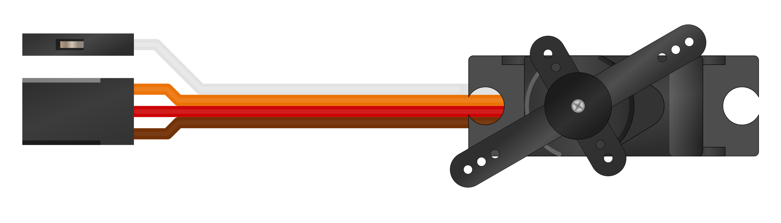
The Adafruit Feedback Servo (Small) has a standard 3-pin connector for control and power, along with an additional wire for feedback. The pinout is as follows:
3-Pin Connector
| Pin Name | Wire Color | Description |
|---|---|---|
| Signal | Orange | PWM control signal input |
| VCC | Red | Power supply (4.8V to 6.0V) |
| GND | Brown | Ground |
Feedback Wire
| Wire Name | Wire Color | Description |
|---|---|---|
| Feedback | Yellow | Analog voltage proportional to servo position |
Usage Instructions
How to Use the Component in a Circuit
- Power the Servo: Connect the red wire (VCC) to a 5V or 6V power source and the brown wire (GND) to ground. Ensure the power supply can handle the current requirements of the servo.
- Control the Servo: Use a PWM signal (typically 50Hz) on the orange wire to control the servo's position. The pulse width determines the angle:
- 1ms pulse: 0° position
- 1.5ms pulse: 90° position (center)
- 2ms pulse: 180° position
- Read Feedback: Connect the yellow feedback wire to an analog input pin on your microcontroller to read the servo's current position. The voltage on this wire is proportional to the servo's angle.
Important Considerations
- Power Supply: Use a stable power source to avoid erratic behavior. If using an Arduino, consider powering the servo with an external power supply to prevent overloading the Arduino's voltage regulator.
- PWM Signal: Ensure the PWM signal is within the servo's specifications (50Hz frequency, 1ms to 2ms pulse width).
- Feedback Wire: The feedback wire provides an analog voltage. Use an ADC (Analog-to-Digital Converter) pin on your microcontroller to read this value.
Example Code for Arduino UNO
Below is an example of how to control the Adafruit Feedback Servo (Small) with an Arduino UNO and read its feedback:
#include <Servo.h> // Include the Servo library

Servo myServo; // Create a Servo object
const int servoPin = 9; // Pin connected to the servo's signal wire
const int feedbackPin = A0; // Pin connected to the servo's feedback wire

void setup() {
  myServo.attach(servoPin); // Attach the servo to the specified pin
  pinMode(feedbackPin, INPUT); // Set the feedback pin as input
  Serial.begin(9600); // Initialize serial communication for debugging
}

void loop() {
  // Move the servo to 90 degrees
  myServo.write(90); // Send a 90° position command
  delay(1000); // Wait for the servo to reach the position

  // Read the feedback voltage
  int feedbackValue = analogRead(feedbackPin); // Read the analog value
  float voltage = feedbackValue * (5.0 / 1023.0); // Convert to voltage

  // Print the feedback voltage to the Serial Monitor
  Serial.print("Feedback Voltage: ");
  Serial.println(voltage);

  delay(1000); // Wait before the next loop iteration
}
Notes on the Code
- The
Servolibrary is used to generate the PWM signal for the servo. - The feedback voltage is read using the
analogRead()function and converted to a voltage value. - Ensure the servo is powered by an external power source if it draws more current than the Arduino can supply.
Troubleshooting and FAQs
Common Issues
Servo Not Moving
- Cause: Incorrect PWM signal or insufficient power supply.
- Solution: Verify the PWM signal is within the specified range (50Hz, 1ms to 2ms pulse width). Check the power supply voltage and current capacity.
Erratic Movement
- Cause: Noise or instability in the power supply.
- Solution: Use a decoupling capacitor (e.g., 100µF) across the power supply lines to stabilize the voltage.
Feedback Voltage Not Changing
- Cause: Feedback wire not connected properly or incorrect analog pin configuration.
- Solution: Ensure the yellow feedback wire is securely connected to an analog input pin. Verify the pin is set as an input in the code.
Overheating
- Cause: Prolonged stall condition or excessive load.
- Solution: Avoid stalling the servo for extended periods. Use a servo with higher torque if the load exceeds the servo's capacity.
FAQs
Q: Can I use this servo with a Raspberry Pi?
A: Yes, but you will need a PWM driver (e.g., Adafruit PCA9685) to generate the required PWM signal, as the Raspberry Pi's GPIO pins do not natively support hardware PWM for servos.
Q: What is the range of the feedback voltage?
A: The feedback voltage typically ranges from 0V to 5V, corresponding to the servo's position from 0° to 180°.
Q: Can I power the servo directly from the Arduino?
A: It is not recommended, as the servo may draw more current than the Arduino can supply. Use an external power source for the servo.
Q: How accurate is the feedback signal?
A: The feedback signal provides a proportional voltage, but its accuracy depends on the servo's internal potentiometer and the resolution of your microcontroller's ADC.
By following this documentation, you can effectively integrate the Adafruit Feedback Servo (Small) into your projects and achieve precise control and monitoring of its position.