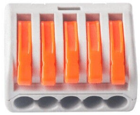
How to Use 5 wire Terminal Connector: Examples, Pinouts, and Specs

 Design with 5 wire Terminal Connector in Cirkit Designer
Introduction
The 5 Wire Terminal Connector is a versatile and reliable component designed to join five wires together in a secure and organized manner. It is commonly used in electrical and electronic circuits to simplify wiring, ensure stable connections, and reduce clutter. This connector is ideal for applications requiring multiple wire connections, such as power distribution, signal routing, and prototyping.
Explore Projects Built with 5 wire Terminal Connector

 Open Project in Cirkit Designer
 Open Project in Cirkit Designer
 Open Project in Cirkit Designer
 Open Project in Cirkit Designer
Explore Projects Built with 5 wire Terminal Connector

 Open Project in Cirkit Designer
 Open Project in Cirkit Designer
 Open Project in Cirkit Designer
 Open Project in Cirkit Designer
Common Applications and Use Cases
- Power distribution in electrical systems
- Signal routing in control panels
- Prototyping and testing circuits
- Home automation and IoT projects
- Industrial equipment wiring
Technical Specifications
The 5 Wire Terminal Connector is designed to handle a wide range of electrical requirements. Below are its key technical details:
| Parameter | Specification |
|---|---|
| Voltage Rating | Up to 300V AC/DC |
| Current Rating | 10A (typical) |
| Wire Size Compatibility | 22 AWG to 12 AWG |
| Material | Flame-retardant plastic, copper alloy |
| Operating Temperature | -40°C to 105°C |
| Mounting Type | Screw terminal or PCB mount |
Pin Configuration and Descriptions
The 5 Wire Terminal Connector typically consists of five screw terminals, each designed to securely hold a single wire. Below is a description of the pin configuration:
| Pin Number | Description |
|---|---|
| 1 | Connection point for wire 1 |
| 2 | Connection point for wire 2 |
| 3 | Connection point for wire 3 |
| 4 | Connection point for wire 4 |
| 5 | Connection point for wire 5 |
Usage Instructions
How to Use the 5 Wire Terminal Connector in a Circuit
- Prepare the Wires: Strip approximately 5-7mm of insulation from the ends of the wires you wish to connect.
- Insert the Wires: Loosen the screws on the terminal connector and insert the stripped ends of the wires into the corresponding slots.
- Secure the Wires: Tighten the screws to ensure a firm connection. Avoid overtightening, as this may damage the wires or the connector.
- Verify the Connection: Gently tug on each wire to confirm it is securely held in place.
Important Considerations and Best Practices
- Ensure the wire gauge is compatible with the connector to avoid loose or improper connections.
- Avoid exceeding the voltage and current ratings to prevent overheating or damage.
- Use a multimeter to check for continuity after making connections.
- If used in high-vibration environments, periodically inspect the screws to ensure they remain tight.
- For PCB-mounted connectors, ensure proper soldering to avoid cold joints.
Example: Connecting to an Arduino UNO
The 5 Wire Terminal Connector can be used to connect multiple sensors or devices to an Arduino UNO. Below is an example of wiring and code to read signals from five sensors:
Wiring
- Connect the output wires of five sensors to the terminal connector.
- Use jumper wires to connect the terminal connector to the Arduino UNO's analog input pins (A0 to A4).
Code
// Example code to read signals from five sensors connected via a 5 Wire Terminal Connector
const int sensorPins[5] = {A0, A1, A2, A3, A4}; // Analog pins for sensors

void setup() {
  Serial.begin(9600); // Initialize serial communication
  for (int i = 0; i < 5; i++) {
    pinMode(sensorPins[i], INPUT); // Set sensor pins as input
  }
}

void loop() {
  for (int i = 0; i < 5; i++) {
    int sensorValue = analogRead(sensorPins[i]); // Read sensor value
    Serial.print("Sensor ");
    Serial.print(i + 1);
    Serial.print(": ");
    Serial.println(sensorValue); // Print sensor value to Serial Monitor
  }
  delay(1000); // Wait 1 second before next reading
}
Troubleshooting and FAQs
Common Issues Users Might Face
- Loose Connections: Wires may come loose if screws are not tightened properly.
- Solution: Ensure screws are securely tightened without damaging the wires.
- Overheating: The connector may overheat if the current exceeds the rated limit.
- Solution: Verify that the current does not exceed 10A and use appropriate wire gauges.
- Intermittent Connections: Poor contact between the wire and terminal can cause intermittent signals.
- Solution: Strip the wire properly and ensure it is fully inserted into the terminal before tightening.
- Corrosion: Over time, the terminals may corrode in humid environments.
- Solution: Use connectors with corrosion-resistant materials or apply a protective coating.
FAQs
Q: Can I use this connector for high-frequency signals?
A: While the connector can handle low-frequency signals, it may not be suitable for high-frequency applications due to potential signal loss or interference.
Q: Is the connector reusable?
A: Yes, the 5 Wire Terminal Connector can be reused multiple times as long as it is not physically damaged.
Q: Can I connect wires of different gauges?
A: Yes, as long as the wire sizes fall within the supported range (22 AWG to 12 AWG).
Q: How do I mount the connector on a PCB?
A: For PCB-mounted versions, solder the connector's pins to the PCB pads, ensuring proper alignment and secure solder joints.