Cirkit Designer Logo
Cirkit Designer
Your all-in-one circuit design IDE
Home / 
Component Documentation

How to Use Voltage Regulator: Examples, Pinouts, and Specs

Image of Voltage Regulator
Cirkit Designer LogoDesign with Voltage Regulator in Cirkit Designer

Introduction

A voltage regulator is an essential electronic component designed to maintain a constant voltage level. It automatically adjusts the voltage output to a set value, ensuring that the connected devices receive a stable and consistent power supply. Voltage regulators are widely used in power supplies for electronic devices, automotive charging systems, and any application where voltage stability is critical.

Explore Projects Built with Voltage Regulator

Use Cirkit Designer to design, explore, and prototype these projects online. Some projects support real-time simulation. Click "Open Project" to start designing instantly!
Battery-Powered LED Control Circuit with Potentiometer and Transistors
Image of STROBE LIGHTS: A project utilizing Voltage Regulator in a practical application
This circuit is a regulated power supply with a 12V battery input, a 7805 voltage regulator providing a 5V output, and a potentiometer for adjustable voltage control. It includes transistors and resistors for current regulation and an LED indicator to show the operational status.
Cirkit Designer LogoOpen Project in Cirkit Designer
AC to DC Power Supply with 7-Segment Voltage Display
Image of BEE PBL: A project utilizing Voltage Regulator in a practical application
This circuit is a regulated power supply that converts 220V AC to a lower, stable DC voltage. It includes a step-down transformer, bridge rectifier, voltage regulator, and filtering capacitors. A 7-segment display indicates the output voltage, which can be adjusted using a potentiometer.
Cirkit Designer LogoOpen Project in Cirkit Designer
LM317 Voltage Regulator Circuit for Adjustable Power Supply with Transformer and Diodes
Image of 12V BULB LIGHT DIMMER CIRCUIT: A project utilizing Voltage Regulator in a practical application
This circuit is a regulated power supply that converts AC voltage to a stable DC voltage. It uses a transformer to step down the AC voltage, diodes for rectification, an electrolytic capacitor for smoothing, and an LM317 voltage regulator to provide a stable output voltage, which is adjustable via a potentiometer. The output powers a bulb.
Cirkit Designer LogoOpen Project in Cirkit Designer
LM317 Voltage Regulator Circuit with Bridge Rectifier for Stable DC Output
Image of voltage regualator using LM317 IC: A project utilizing Voltage Regulator in a practical application
This circuit converts 220V AC to a regulated DC voltage using a bridge rectifier, smoothing capacitors, and an LM317 voltage regulator. The output voltage can be adjusted using a potentiometer connected to the LM317's adjustment pin.
Cirkit Designer LogoOpen Project in Cirkit Designer

Explore Projects Built with Voltage Regulator

Use Cirkit Designer to design, explore, and prototype these projects online. Some projects support real-time simulation. Click "Open Project" to start designing instantly!
Image of STROBE LIGHTS: A project utilizing Voltage Regulator in a practical application
Battery-Powered LED Control Circuit with Potentiometer and Transistors
This circuit is a regulated power supply with a 12V battery input, a 7805 voltage regulator providing a 5V output, and a potentiometer for adjustable voltage control. It includes transistors and resistors for current regulation and an LED indicator to show the operational status.
Cirkit Designer LogoOpen Project in Cirkit Designer
Image of BEE PBL: A project utilizing Voltage Regulator in a practical application
AC to DC Power Supply with 7-Segment Voltage Display
This circuit is a regulated power supply that converts 220V AC to a lower, stable DC voltage. It includes a step-down transformer, bridge rectifier, voltage regulator, and filtering capacitors. A 7-segment display indicates the output voltage, which can be adjusted using a potentiometer.
Cirkit Designer LogoOpen Project in Cirkit Designer
Image of 12V BULB LIGHT DIMMER CIRCUIT: A project utilizing Voltage Regulator in a practical application
LM317 Voltage Regulator Circuit for Adjustable Power Supply with Transformer and Diodes
This circuit is a regulated power supply that converts AC voltage to a stable DC voltage. It uses a transformer to step down the AC voltage, diodes for rectification, an electrolytic capacitor for smoothing, and an LM317 voltage regulator to provide a stable output voltage, which is adjustable via a potentiometer. The output powers a bulb.
Cirkit Designer LogoOpen Project in Cirkit Designer
Image of voltage regualator using LM317 IC: A project utilizing Voltage Regulator in a practical application
LM317 Voltage Regulator Circuit with Bridge Rectifier for Stable DC Output
This circuit converts 220V AC to a regulated DC voltage using a bridge rectifier, smoothing capacitors, and an LM317 voltage regulator. The output voltage can be adjusted using a potentiometer connected to the LM317's adjustment pin.
Cirkit Designer LogoOpen Project in Cirkit Designer

Common Applications and Use Cases

  • Power supplies for electronic circuits
  • Automotive battery charging systems
  • Solar power systems
  • Voltage regulation for sensitive electronics like microcontrollers and sensors
  • Embedded systems requiring stable power supply

Technical Specifications

Voltage regulators come in various types, including linear regulators and switching regulators, each with its own set of specifications. Below is a generic table for a common linear voltage regulator, such as the LM7805.

Specification Value/Description
Output Voltage 5V
Input Voltage Range 7V to 25V
Output Current Up to 1A
Dropout Voltage ~2V
Package Type TO-220
Operating Temperature Range 0°C to 125°C

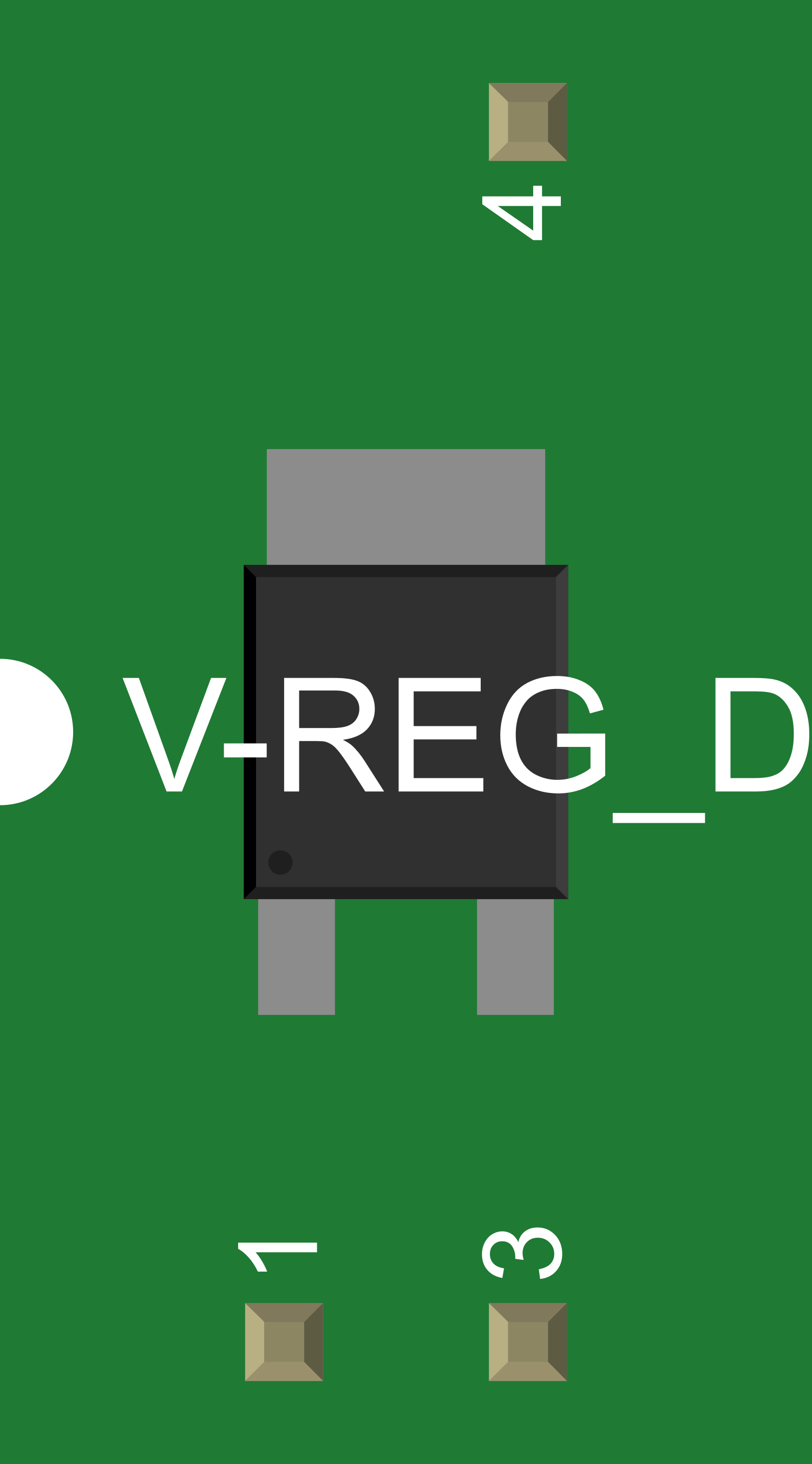
Pin Configuration and Descriptions

Pin Number Name Description
1 Input Connects to the unregulated input voltage
2 Ground Common reference for input and output; connected to system ground
3 Output Regulated output voltage is provided here
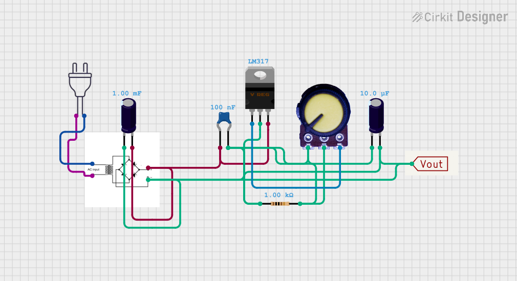
Usage Instructions

How to Use the Voltage Regulator in a Circuit

  1. Connect the unregulated input voltage to the Input pin.
  2. Connect the Ground pin to the system ground.
  3. The Output pin will provide the regulated voltage.
  4. It is recommended to place a capacitor (typically 0.33µF) close to the Input pin and another capacitor (typically 0.1µF) close to the Output pin to filter out noise and provide stability.

Important Considerations and Best Practices

  • Ensure the input voltage is within the specified range for the regulator.
  • Do not exceed the maximum output current rating.
  • Use heat sinks if the regulator is expected to dissipate significant power.
  • Keep the regulator away from high-temperature sources to prevent overheating.
  • Place input and output capacitors as close to the regulator pins as possible.

Troubleshooting and FAQs

Common Issues

  • Voltage Drop: If the input voltage is too close to the desired output voltage, the regulator may not be able to maintain the output voltage (dropout voltage issue).
  • Overheating: If the regulator is dissipating too much power, it may overheat and shut down.
  • Noise: Poor filtering or layout can result in a noisy output voltage.

Solutions and Tips for Troubleshooting

  • Ensure the input voltage is at least a few volts higher than the output voltage.
  • Use a heat sink to dissipate heat if the regulator is running hot.
  • Check the capacitors for proper values and ensure they are in good condition.
  • Verify the integrity of the connections and the absence of short circuits.

FAQs

Q: Can I increase the output current of a voltage regulator? A: The output current cannot be increased beyond the maximum rating of the regulator. However, you can parallel multiple regulators with proper current sharing or use a regulator with a higher current rating.

Q: What happens if the input voltage drops below the minimum required? A: The regulator may not be able to maintain the regulated output voltage, resulting in a lower output voltage.

Q: Can I use a voltage regulator to step up voltage? A: No, a standard linear voltage regulator cannot step up voltage. You would need a boost converter or a different type of switching regulator for that purpose.

Example Connection with Arduino UNO

// No specific code is required for using a voltage regulator with an Arduino UNO.
// The regulator is used to provide a stable 5V to the Arduino's 5V pin if needed.

// However, here is an example of how to read the regulated voltage using an analog pin.

void setup() {
  Serial.begin(9600);
}

void loop() {
  int sensorValue = analogRead(A0); // Connect the regulated 5V to A0
  float voltage = sensorValue * (5.0 / 1023.0); // Convert the reading to voltage
  Serial.println(voltage); // Print the voltage to the Serial Monitor
  delay(1000); // Wait for a second
}

Remember to connect the ground of the voltage regulator to the ground of the Arduino to complete the circuit.