Cirkit Designer Logo
Cirkit Designer
Your all-in-one circuit design IDE
Home / 
Component Documentation

How to Use Waveshare ESP32-S3-POE-ETH: Examples, Pinouts, and Specs

Image of Waveshare ESP32-S3-POE-ETH
Cirkit Designer LogoDesign with Waveshare ESP32-S3-POE-ETH in Cirkit Designer

Introduction

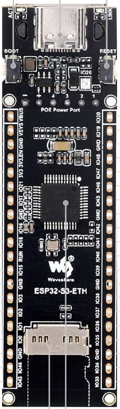
The Waveshare ESP32-S3-POE-ETH is a versatile development board that integrates the powerful ESP32-S3 microcontroller with Power over Ethernet (PoE) functionality and Ethernet connectivity. Designed for IoT applications, this board is ideal for scenarios requiring reliable network access, such as smart home systems, industrial automation, and remote monitoring.

Key features of the ESP32-S3 microcontroller include dual-core Xtensa LX7 processors, Wi-Fi 802.11 b/g/n, Bluetooth 5.0 (LE), and a rich set of peripherals. The addition of PoE support allows the board to be powered directly through an Ethernet cable, simplifying deployment in environments where power outlets are limited.

Explore Projects Built with Waveshare ESP32-S3-POE-ETH

Use Cirkit Designer to design, explore, and prototype these projects online. Some projects support real-time simulation. Click "Open Project" to start designing instantly!
ESP32-Based Environmental Monitoring and Home Automation System with Ethernet Connectivity
Image of ESP32 30Pin 3Phase AC Box W5500 Ethernet Standard: A project utilizing Waveshare ESP32-S3-POE-ETH in a practical application
This circuit features an ESP32 microcontroller interfaced with a W5500 Ethernet module for network connectivity, a DHT22 sensor for measuring temperature and humidity, a ZMPT101B module for AC voltage sensing, and an Adafruit SHTC3 sensor for additional temperature and humidity readings. The ESP32 also controls a 4-channel relay module for switching external devices. The sensors and Ethernet module communicate with the ESP32 via GPIO pins, with the W5500 using SPI and the SHTC3 using I2C. Common ground and power lines are shared among the components.
Cirkit Designer LogoOpen Project in Cirkit Designer
ESP32-Based LoRa Communication Device with OLED Display
Image of LoRa_Satellite_GS: A project utilizing Waveshare ESP32-S3-POE-ETH in a practical application
This circuit features an ESP32 microcontroller connected to a 0.96" OLED display and a LoRa Ra-02 SX1278 module for wireless communication. The ESP32 facilitates communication with the OLED display via I2C (SDA and SCK lines) and with the LoRa module via SPI (MISO, MOSI, SCK, NSS lines) and GPIO for control signals (DI00, DI01, RST). The circuit is designed for applications requiring wireless data transmission and visual data display.
Cirkit Designer LogoOpen Project in Cirkit Designer
ESP32-S3 Based Smart IoT Distance Sensor with Ethernet Connectivity
Image of ttt: A project utilizing Waveshare ESP32-S3-POE-ETH in a practical application
This circuit features an ESP32-S3 microcontroller interfaced with a KY-019 Relay module, a VL53L1X time-of-flight sensor, and a W5500 Ethernet module. The ESP32-S3 controls the relay and communicates with the VL53L1X sensor via I2C, as well as with the network through the Ethernet module. An AC source is converted to DC for powering the components, and a micro USB connection is used to trigger the relay.
Cirkit Designer LogoOpen Project in Cirkit Designer
ESP32 and W5500 Ethernet Module Based Smart Energy Monitor
Image of ESP32 30Pin 8 Ch Micro and USBC: A project utilizing Waveshare ESP32-S3-POE-ETH in a practical application
This circuit features an ESP32 microcontroller interfaced with a W5500 Ethernet module for network connectivity and a ZMPT101B module for AC voltage sensing. Additionally, a DHT22 sensor is connected to the ESP32 for measuring temperature and humidity. The ESP32 manages data acquisition from the sensors and communication over Ethernet.
Cirkit Designer LogoOpen Project in Cirkit Designer

Explore Projects Built with Waveshare ESP32-S3-POE-ETH

Use Cirkit Designer to design, explore, and prototype these projects online. Some projects support real-time simulation. Click "Open Project" to start designing instantly!
Image of ESP32 30Pin 3Phase AC Box W5500 Ethernet Standard: A project utilizing Waveshare ESP32-S3-POE-ETH in a practical application
ESP32-Based Environmental Monitoring and Home Automation System with Ethernet Connectivity
This circuit features an ESP32 microcontroller interfaced with a W5500 Ethernet module for network connectivity, a DHT22 sensor for measuring temperature and humidity, a ZMPT101B module for AC voltage sensing, and an Adafruit SHTC3 sensor for additional temperature and humidity readings. The ESP32 also controls a 4-channel relay module for switching external devices. The sensors and Ethernet module communicate with the ESP32 via GPIO pins, with the W5500 using SPI and the SHTC3 using I2C. Common ground and power lines are shared among the components.
Cirkit Designer LogoOpen Project in Cirkit Designer
Image of LoRa_Satellite_GS: A project utilizing Waveshare ESP32-S3-POE-ETH in a practical application
ESP32-Based LoRa Communication Device with OLED Display
This circuit features an ESP32 microcontroller connected to a 0.96" OLED display and a LoRa Ra-02 SX1278 module for wireless communication. The ESP32 facilitates communication with the OLED display via I2C (SDA and SCK lines) and with the LoRa module via SPI (MISO, MOSI, SCK, NSS lines) and GPIO for control signals (DI00, DI01, RST). The circuit is designed for applications requiring wireless data transmission and visual data display.
Cirkit Designer LogoOpen Project in Cirkit Designer
Image of ttt: A project utilizing Waveshare ESP32-S3-POE-ETH in a practical application
ESP32-S3 Based Smart IoT Distance Sensor with Ethernet Connectivity
This circuit features an ESP32-S3 microcontroller interfaced with a KY-019 Relay module, a VL53L1X time-of-flight sensor, and a W5500 Ethernet module. The ESP32-S3 controls the relay and communicates with the VL53L1X sensor via I2C, as well as with the network through the Ethernet module. An AC source is converted to DC for powering the components, and a micro USB connection is used to trigger the relay.
Cirkit Designer LogoOpen Project in Cirkit Designer
Image of ESP32 30Pin 8 Ch Micro and USBC: A project utilizing Waveshare ESP32-S3-POE-ETH in a practical application
ESP32 and W5500 Ethernet Module Based Smart Energy Monitor
This circuit features an ESP32 microcontroller interfaced with a W5500 Ethernet module for network connectivity and a ZMPT101B module for AC voltage sensing. Additionally, a DHT22 sensor is connected to the ESP32 for measuring temperature and humidity. The ESP32 manages data acquisition from the sensors and communication over Ethernet.
Cirkit Designer LogoOpen Project in Cirkit Designer

Common Applications

  • Smart home devices and automation
  • Industrial IoT systems
  • Remote monitoring and control
  • Networked sensors and data loggers
  • Edge computing and AI applications

Technical Specifications

Key Technical Details

Parameter Specification
Microcontroller ESP32-S3 (Xtensa® 32-bit LX7 dual-core processor)
Clock Speed Up to 240 MHz
Flash Memory 16 MB
PSRAM 8 MB
Connectivity Wi-Fi 802.11 b/g/n, Bluetooth 5.0 (LE), Ethernet
Ethernet 10/100 Mbps Ethernet with PoE (IEEE 802.3af compliant)
GPIO Pins 36 GPIOs (multiplexed with other functions)
Operating Voltage 3.3V
Power Input PoE (via Ethernet) or 5V via USB-C
Dimensions 88mm x 25mm
Operating Temperature -40°C to +85°C

Pin Configuration and Descriptions

The Waveshare ESP32-S3-POE-ETH features a variety of pins for interfacing with peripherals. Below is the pinout description:

Pin Name Function
VIN Power input (5V via USB-C)
GND Ground
GPIO0 General-purpose I/O, used for boot mode selection
GPIO1-36 General-purpose I/O pins, multiplexed with UART, I2C, SPI, PWM, etc.
TXD0/RXD0 UART0 transmit/receive (default serial communication)
SCL/SDA I2C clock and data lines
MOSI/MISO SPI data lines
ETH_TX+/TX- Ethernet transmit pair
ETH_RX+/RX- Ethernet receive pair
PoE Pins Power over Ethernet input (IEEE 802.3af compliant)

Usage Instructions

How to Use the Component in a Circuit

  1. Powering the Board:

    • Connect the board to an Ethernet cable with PoE support to power it directly.
    • Alternatively, use a USB-C cable to supply 5V power.
  2. Programming the Board:

    • Install the ESP32-S3 board package in the Arduino IDE or use the ESP-IDF framework.
    • Connect the board to your computer via USB-C for programming and debugging.
  3. Connecting Peripherals:

    • Use the GPIO pins to interface with sensors, actuators, or other devices.
    • Configure the pins in your code for the desired functionality (e.g., digital I/O, PWM, I2C, SPI).
  4. Ethernet Configuration:

    • Connect the board to a network using an Ethernet cable.
    • Configure the Ethernet settings in your code (e.g., static IP or DHCP).

Important Considerations and Best Practices

  • Ensure the Ethernet cable and PoE injector/switch comply with IEEE 802.3af standards.
  • Avoid exceeding the maximum current draw of the GPIO pins (typically 40mA per pin).
  • Use level shifters if interfacing with 5V logic devices, as the board operates at 3.3V.
  • When using Wi-Fi and Ethernet simultaneously, manage the network interfaces carefully in your code.

Example Code for Arduino IDE

Below is an example of how to configure the Ethernet interface and blink an LED connected to GPIO2:

#include <ETH.h> // Include Ethernet library for ESP32

#define LED_PIN 2 // Define the GPIO pin for the LED

void setup() {
  pinMode(LED_PIN, OUTPUT); // Set LED pin as output

  // Initialize Ethernet with default settings (DHCP)
  ETH.begin();

  // Wait for Ethernet connection
  while (!ETH.linkUp()) {
    delay(100);
    Serial.println("Waiting for Ethernet connection...");
  }

  Serial.println("Ethernet connected!");
  Serial.print("IP Address: ");
  Serial.println(ETH.localIP());
}

void loop() {
  // Blink the LED
  digitalWrite(LED_PIN, HIGH); // Turn LED on
  delay(500);                  // Wait 500ms
  digitalWrite(LED_PIN, LOW);  // Turn LED off
  delay(500);                  // Wait 500ms
}

Troubleshooting and FAQs

Common Issues and Solutions

  1. Board Not Powering On:

    • Ensure the Ethernet cable is connected to a PoE-enabled switch or injector.
    • If using USB-C, verify the cable and power source are functioning correctly.
  2. Ethernet Not Connecting:

    • Check the Ethernet cable and network connection.
    • Verify that the PoE switch or injector is IEEE 802.3af compliant.
    • Ensure the Ethernet settings in your code (e.g., DHCP or static IP) are correct.
  3. Wi-Fi and Ethernet Conflicts:

    • When using both Wi-Fi and Ethernet, ensure proper configuration in your code to avoid conflicts.
    • Use separate tasks or threads to manage network interfaces.
  4. GPIO Pin Not Responding:

    • Verify the pin configuration in your code.
    • Check for short circuits or incorrect wiring.

FAQs

Q: Can I use this board without PoE?
A: Yes, the board can be powered via the USB-C port with a 5V power source.

Q: Does the board support simultaneous Wi-Fi and Ethernet?
A: Yes, the ESP32-S3 supports simultaneous use of Wi-Fi and Ethernet, but proper configuration is required.

Q: What is the maximum current draw for the GPIO pins?
A: Each GPIO pin can source or sink up to 40mA, but it is recommended to stay below this limit for reliable operation.

Q: How do I update the firmware?
A: Connect the board via USB-C to your computer and use the Arduino IDE or ESP-IDF to upload the firmware.


This concludes the documentation for the Waveshare ESP32-S3-POE-ETH. For further details, refer to the official Waveshare product page or datasheet.