How to Use L298N: Examples, Pinouts, and Specs
Introduction
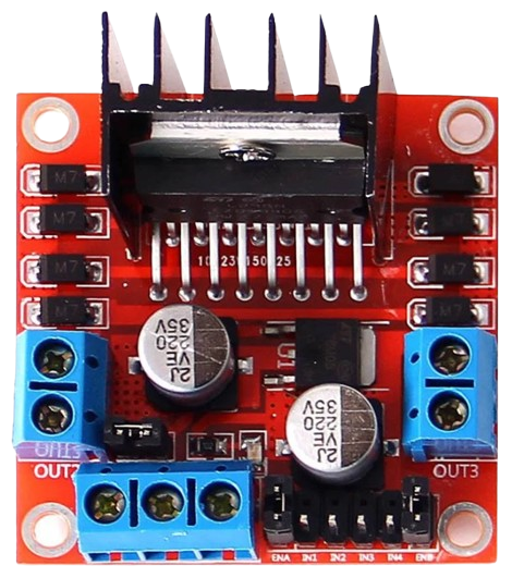
The L298N is a dual H-bridge motor driver IC designed to control the direction and speed of DC motors and stepper motors. It is capable of driving two motors simultaneously, making it a versatile choice for robotics, automation, and other motor control applications. The L298N can handle high currents and voltages, making it suitable for a wide range of projects, from small robots to industrial automation systems.
Explore Projects Built with L298N
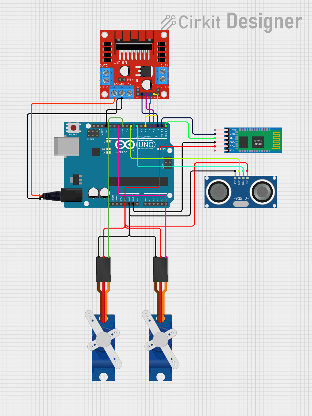
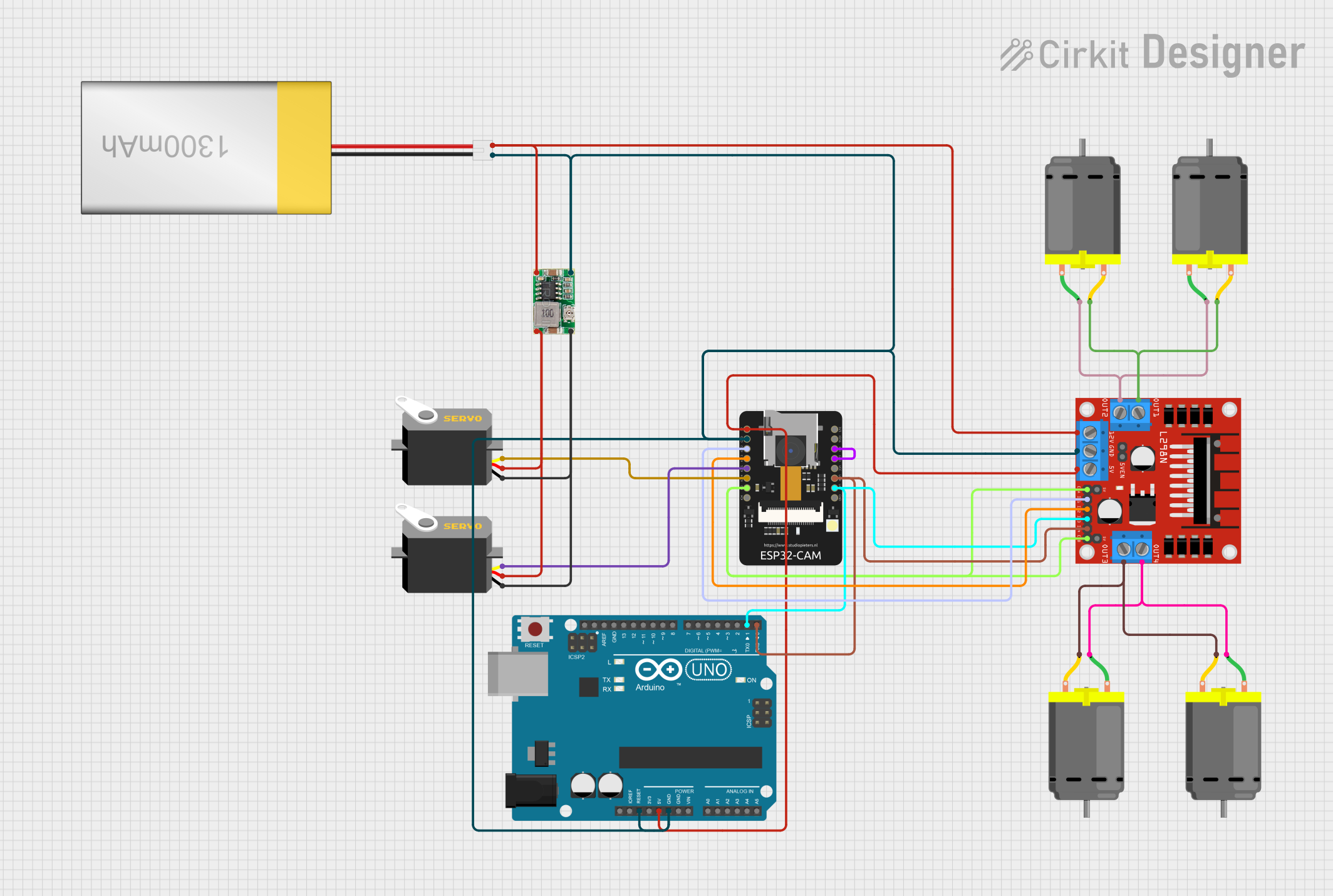
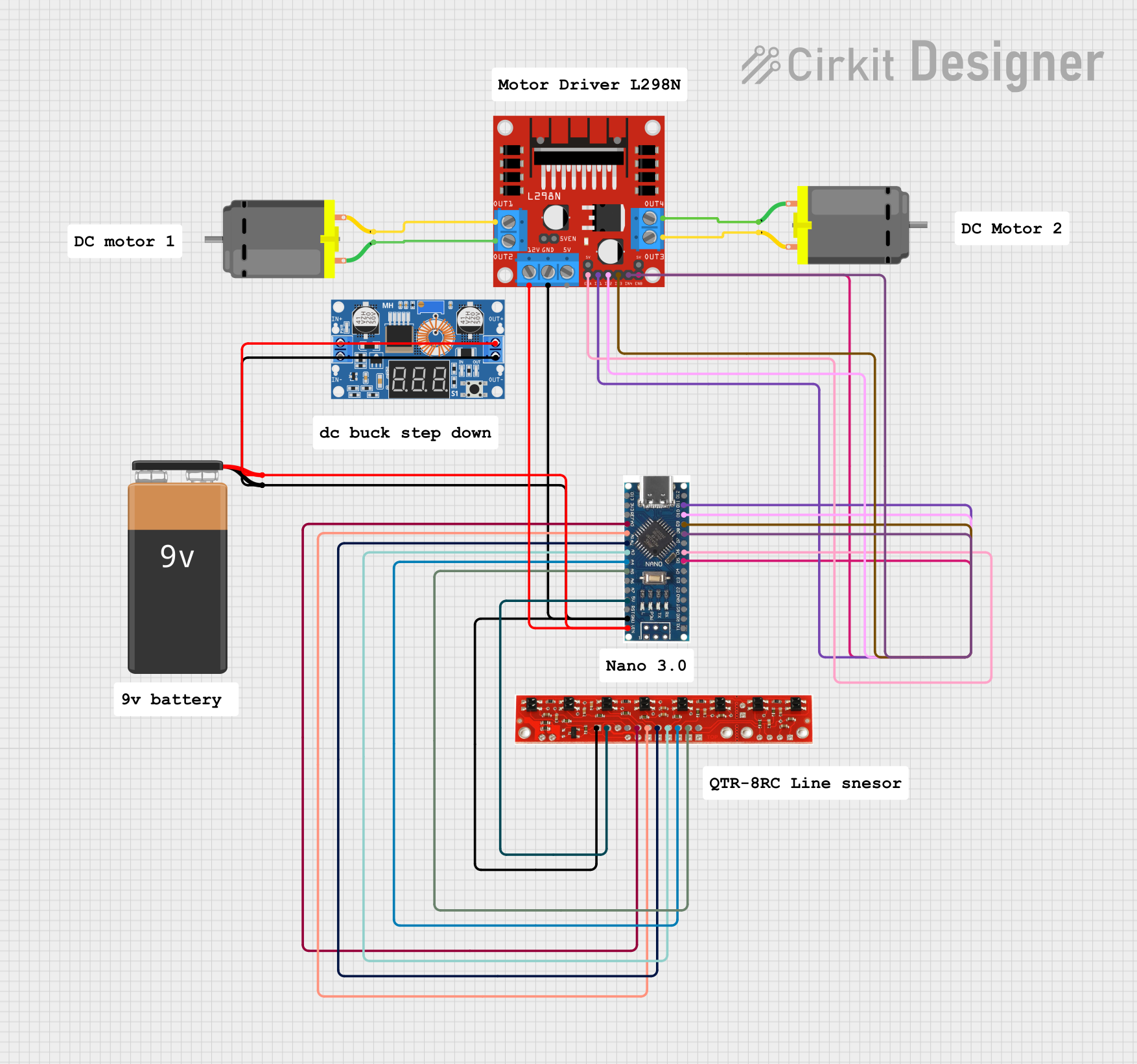

Explore Projects Built with L298N
Common Applications:
- Robotics (e.g., controlling wheels or robotic arms)
- Automation systems
- Conveyor belts
- Stepper motor control
- DIY motorized projects
Technical Specifications
The L298N is a robust and reliable motor driver IC with the following key specifications:
| Parameter | Value |
|---|---|
| Operating Voltage | 5V to 46V |
| Maximum Output Current | 2A per channel (4A total) |
| Logic Voltage | 5V |
| Power Dissipation | 25W (with proper heat sinking) |
| Control Logic Levels | High: 2.3V to 5V, Low: 0V to 1.5V |
| Number of Channels | 2 (dual H-bridge) |
| Motor Types Supported | DC motors, stepper motors |
| Operating Temperature | -25°C to +130°C |
Pin Configuration and Descriptions
The L298N module typically comes with a breakout board for easier use. Below is the pin configuration for the module:
| Pin Name | Type | Description |
|---|---|---|
| IN1 | Input | Controls the direction of Motor A (High/Low). |
| IN2 | Input | Controls the direction of Motor A (High/Low). |
| IN3 | Input | Controls the direction of Motor B (High/Low). |
| IN4 | Input | Controls the direction of Motor B (High/Low). |
| ENA | Enable/Input | Enables or disables Motor A. Can be used for PWM speed control. |
| ENB | Enable/Input | Enables or disables Motor B. Can be used for PWM speed control. |
| OUT1 | Output | Motor A terminal 1. |
| OUT2 | Output | Motor A terminal 2. |
| OUT3 | Output | Motor B terminal 1. |
| OUT4 | Output | Motor B terminal 2. |
| VCC | Power Input | Motor power supply (5V to 46V). |
| GND | Ground | Common ground for the circuit. |
| 5V | Power Output | Provides 5V output (used when the onboard regulator is active). |
Usage Instructions
How to Use the L298N in a Circuit
Power Connections:
- Connect the motor power supply to the
VCCpin (ensure it matches the motor's voltage rating). - Connect the
GNDpin to the ground of your power supply and microcontroller. - If your motor power supply is above 7V, you can use the onboard 5V regulator to power your microcontroller by connecting the
5Vpin to the microcontroller's 5V input.
- Connect the motor power supply to the
Motor Connections:
- Connect the motor terminals to the
OUT1andOUT2pins for Motor A, andOUT3andOUT4pins for Motor B.
- Connect the motor terminals to the
Control Connections:
- Use the
IN1andIN2pins to control the direction of Motor A, andIN3andIN4for Motor B. - Use the
ENAandENBpins for speed control via PWM signals.
- Use the
Logic Power:
- Provide 5V logic power to the control pins from your microcontroller.
Example Arduino Code
Below is an example of how to control a DC motor using the L298N and an Arduino UNO:
// Define control pins for Motor A
const int IN1 = 9;  // Direction control pin 1 for Motor A
const int IN2 = 8;  // Direction control pin 2 for Motor A
const int ENA = 10; // Speed control (PWM) pin for Motor A

void setup() {
  // Set motor control pins as outputs
  pinMode(IN1, OUTPUT);
  pinMode(IN2, OUTPUT);
  pinMode(ENA, OUTPUT);
}

void loop() {
  // Rotate Motor A forward at 50% speed
  digitalWrite(IN1, HIGH);  // Set IN1 high
  digitalWrite(IN2, LOW);   // Set IN2 low
  analogWrite(ENA, 128);    // Set ENA to 50% duty cycle (128/255)

  delay(2000); // Run motor for 2 seconds

  // Rotate Motor A backward at 75% speed
  digitalWrite(IN1, LOW);   // Set IN1 low
  digitalWrite(IN2, HIGH);  // Set IN2 high
  analogWrite(ENA, 192);    // Set ENA to 75% duty cycle (192/255)

  delay(2000); // Run motor for 2 seconds

  // Stop Motor A
  digitalWrite(IN1, LOW);   // Set IN1 low
  digitalWrite(IN2, LOW);   // Set IN2 low
  analogWrite(ENA, 0);      // Set ENA to 0% duty cycle (motor off)

  delay(2000); // Wait for 2 seconds before repeating
}
Important Considerations and Best Practices
- Heat Dissipation: The L298N can get hot during operation. Use a heat sink or active cooling for high-current applications.
- Power Supply: Ensure the motor power supply voltage matches the motor's requirements and does not exceed the L298N's maximum voltage rating.
- Current Limitation: The L298N can handle up to 2A per channel. For higher currents, consider using a different motor driver.
- PWM Frequency: Use a PWM frequency between 1kHz and 20kHz for optimal performance.
Troubleshooting and FAQs
Common Issues and Solutions
Motors Not Running:
- Check all power connections and ensure the motor power supply is sufficient.
- Verify that the
ENAorENBpins are enabled (HIGH or receiving a PWM signal).
Overheating:
- Ensure the L298N has a heat sink attached.
- Reduce the motor load or use a lower current motor.
Erratic Motor Behavior:
- Check for loose connections or poor solder joints.
- Ensure the control signals from the microcontroller are correct.
No 5V Output:
- Ensure the onboard regulator jumper is in place.
- Verify that the motor power supply is above 7V.
FAQs
Q: Can the L298N drive stepper motors?
A: Yes, the L298N can drive bipolar stepper motors by controlling the two H-bridges. You will need to sequence the control signals appropriately.
Q: Can I use the L298N with a 3.3V microcontroller?
A: The L298N is designed for 5V logic levels. You may need a level shifter to interface it with a 3.3V microcontroller.
Q: What is the maximum motor voltage the L298N can handle?
A: The L298N can handle motor voltages up to 46V.
Q: Can I control the speed of the motors?
A: Yes, you can control motor speed using PWM signals on the ENA and ENB pins.
By following this documentation, you can effectively use the L298N motor driver in your projects!