Cirkit Designer Logo
Cirkit Designer
Your all-in-one circuit design IDE
Home / 
Component Documentation

How to Use ATME ASDC 30 AD0: Examples, Pinouts, and Specs
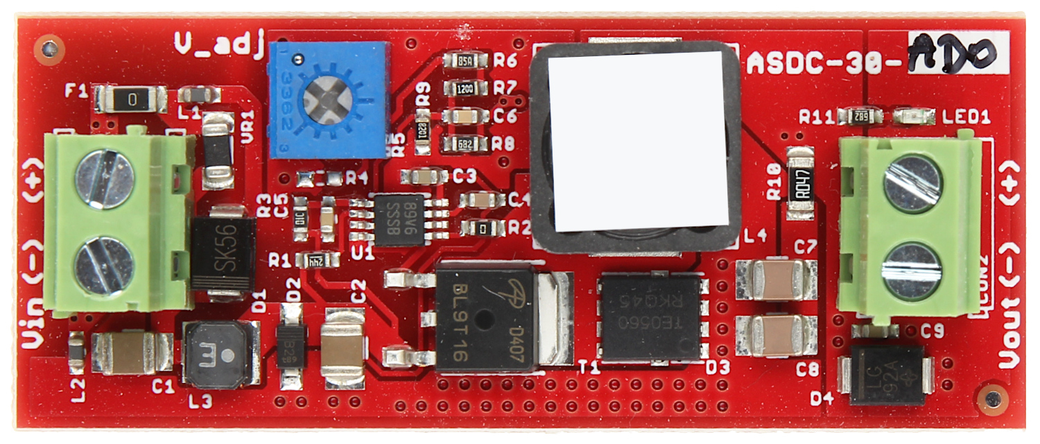

Image of ATME ASDC 30 AD0
Cirkit Designer LogoDesign with ATME ASDC 30 AD0 in Cirkit Designer

Introduction

The ATME ASDC 30 AD0 is a high-performance microcontroller designed for a wide range of embedded applications. Manufactured by ATME, this microcontroller combines advanced processing capabilities with integrated peripherals, making it suitable for applications such as IoT devices, industrial automation, robotics, and consumer electronics. Its support for multiple communication protocols ensures seamless integration into complex systems.

Explore Projects Built with ATME ASDC 30 AD0
Use Cirkit Designer to design, explore, and prototype these projects online. Some projects support real-time simulation. Click "Open Project" to start designing instantly!
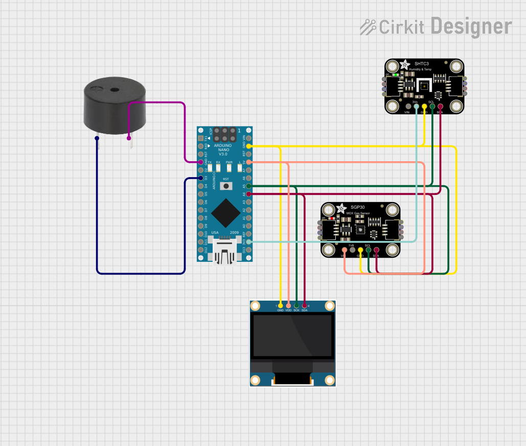
Arduino Nano-Based Air Quality Monitor with OLED Display and Alert Buzzer
Image of Luftkvalitetsmätare: A project utilizing ATME ASDC 30 AD0 in a practical application
This circuit features an Arduino Nano microcontroller interfaced with an Adafruit SGP30 air quality sensor, an Adafruit SHTC3 temperature and humidity sensor, and a 0.96" OLED display for real-time environmental monitoring. The sensors communicate with the Arduino via I2C, with the SGP30 and SHTC3 sensors providing air quality readings (CO2 and TVOC) and temperature/humidity data, respectively, which are then displayed on the OLED. Additionally, a buzzer is connected to the Arduino and is programmed to activate when CO2 levels exceed a certain threshold, serving as an alert system.
Cirkit Designer LogoOpen Project in Cirkit Designer
Wi-Fi Enabled Sensor Hub with ESP8266 and ADS1115 ADC
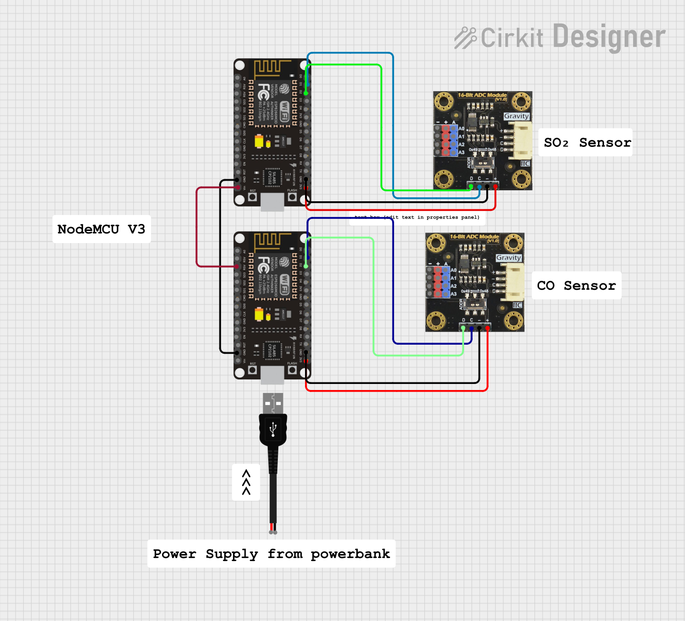
Image of Node Mcu Gas Sensor: A project utilizing ATME ASDC 30 AD0 in a practical application
This circuit features two ESP8266 NodeMCU microcontrollers, each interfaced with a Gravity I2C ADS1115 16-Bit ADC module for analog-to-digital conversion. The microcontrollers communicate with the ADC modules via I2C protocol, with one set of connections for each microcontroller-ADC pair, and are powered through a common 3.3V and ground connection.
Cirkit Designer LogoOpen Project in Cirkit Designer
Solar-Powered Environmental Data Logger with Adafruit Feather M0 Express
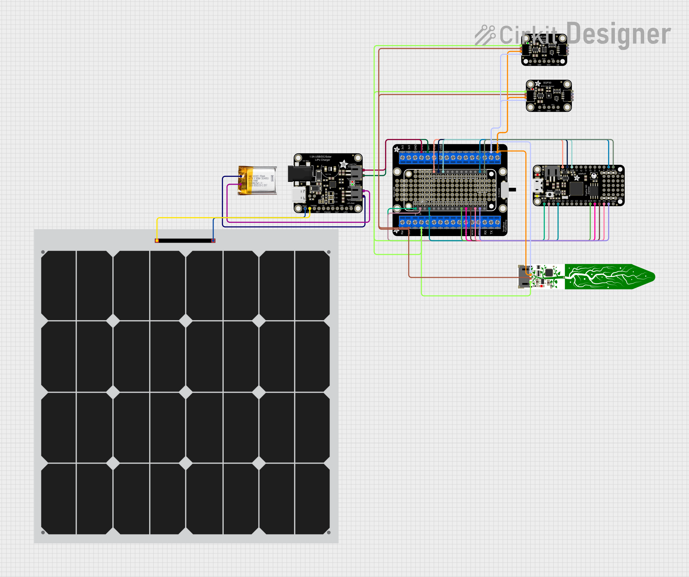
Image of Lake Thoreau Monitoring Station: A project utilizing ATME ASDC 30 AD0 in a practical application
This circuit is designed for environmental data collection and logging, utilizing an Adafruit Feather M0 Express microcontroller as the central processing unit. It interfaces with a BME280 sensor for atmospheric temperature, humidity, and pressure measurements, an SGP30 sensor for monitoring air quality (eCO2 and TVOC), and a STEMMA soil sensor for detecting soil moisture and temperature. The system is powered by a solar panel and a 3.7v LiPo battery, managed by an Adafruit BQ24074 Solar-DC-USB Lipo Charger, and provides easy access to the microcontroller's connections through an Adafruit Terminal Breakout FeatherWing.
Cirkit Designer LogoOpen Project in Cirkit Designer
Arduino Nano-Controlled LED Display with RTC and Humidity Sensing
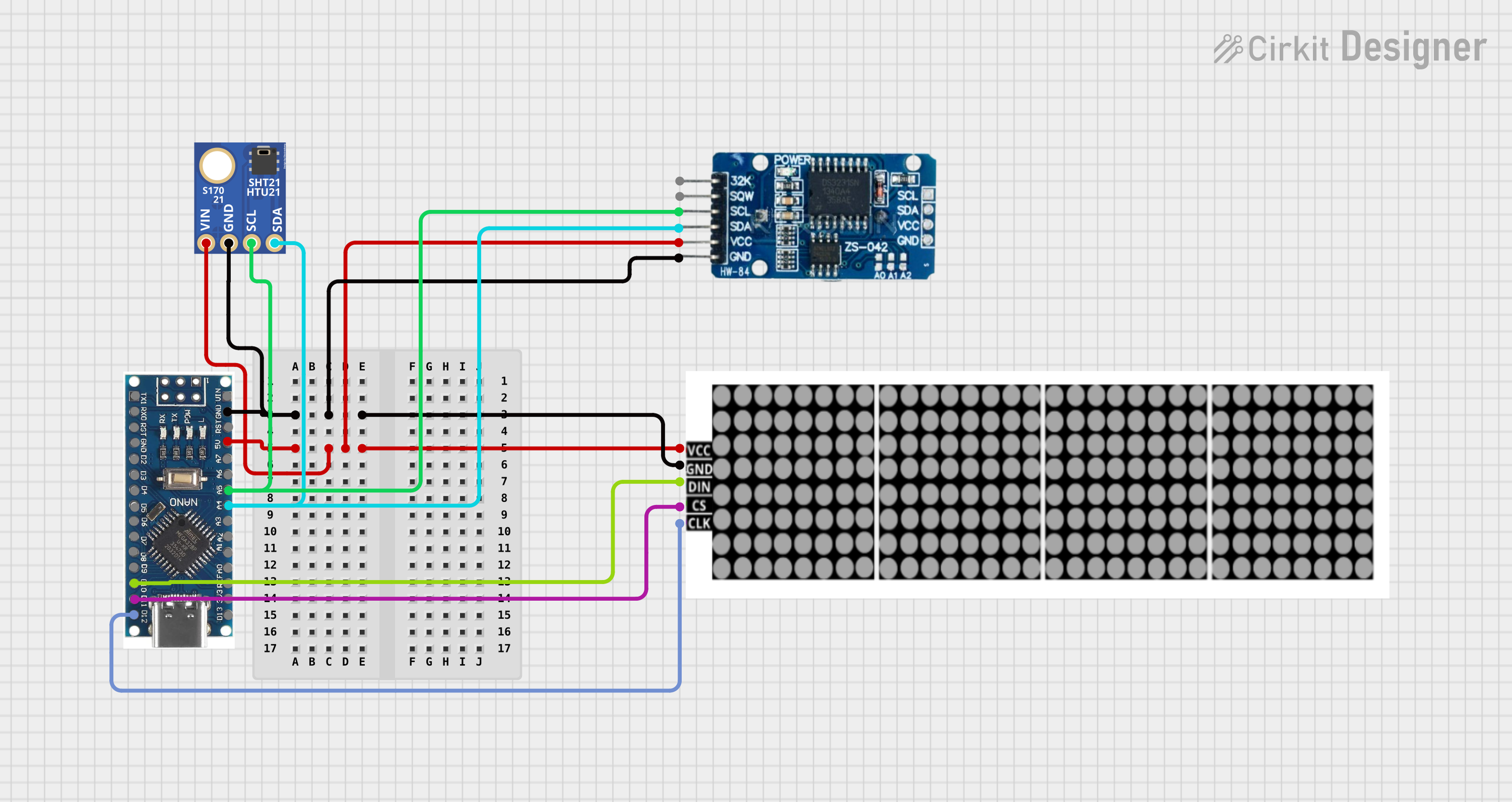
Image of Alarm Clock: A project utilizing ATME ASDC 30 AD0 in a practical application
This circuit features a Nano 3.0 ATmega328P microcontroller connected to an LED dot display, a real-time clock (RTC DS3231), and a humidity and temperature sensor (SHT21). The microcontroller communicates with the RTC and SHT21 via I2C (using A4 and A5 as SDA and SCL lines, respectively), and it controls the LED display through SPI-like signals (using D10, D11, and D12 for DIN, CS, and CLK). The circuit is designed to display time and environmental data on the LED display, with all components sharing a common power supply and ground.
Cirkit Designer LogoOpen Project in Cirkit Designer

Explore Projects Built with ATME ASDC 30 AD0

Use Cirkit Designer to design, explore, and prototype these projects online. Some projects support real-time simulation. Click "Open Project" to start designing instantly!
Image of Luftkvalitetsmätare: A project utilizing ATME ASDC 30 AD0 in a practical application
Arduino Nano-Based Air Quality Monitor with OLED Display and Alert Buzzer
This circuit features an Arduino Nano microcontroller interfaced with an Adafruit SGP30 air quality sensor, an Adafruit SHTC3 temperature and humidity sensor, and a 0.96" OLED display for real-time environmental monitoring. The sensors communicate with the Arduino via I2C, with the SGP30 and SHTC3 sensors providing air quality readings (CO2 and TVOC) and temperature/humidity data, respectively, which are then displayed on the OLED. Additionally, a buzzer is connected to the Arduino and is programmed to activate when CO2 levels exceed a certain threshold, serving as an alert system.
Cirkit Designer LogoOpen Project in Cirkit Designer
Image of Node Mcu Gas Sensor: A project utilizing ATME ASDC 30 AD0 in a practical application
Wi-Fi Enabled Sensor Hub with ESP8266 and ADS1115 ADC
This circuit features two ESP8266 NodeMCU microcontrollers, each interfaced with a Gravity I2C ADS1115 16-Bit ADC module for analog-to-digital conversion. The microcontrollers communicate with the ADC modules via I2C protocol, with one set of connections for each microcontroller-ADC pair, and are powered through a common 3.3V and ground connection.
Cirkit Designer LogoOpen Project in Cirkit Designer
Image of Lake Thoreau Monitoring Station: A project utilizing ATME ASDC 30 AD0 in a practical application
Solar-Powered Environmental Data Logger with Adafruit Feather M0 Express
This circuit is designed for environmental data collection and logging, utilizing an Adafruit Feather M0 Express microcontroller as the central processing unit. It interfaces with a BME280 sensor for atmospheric temperature, humidity, and pressure measurements, an SGP30 sensor for monitoring air quality (eCO2 and TVOC), and a STEMMA soil sensor for detecting soil moisture and temperature. The system is powered by a solar panel and a 3.7v LiPo battery, managed by an Adafruit BQ24074 Solar-DC-USB Lipo Charger, and provides easy access to the microcontroller's connections through an Adafruit Terminal Breakout FeatherWing.
Cirkit Designer LogoOpen Project in Cirkit Designer
Image of Alarm Clock: A project utilizing ATME ASDC 30 AD0 in a practical application
Arduino Nano-Controlled LED Display with RTC and Humidity Sensing
This circuit features a Nano 3.0 ATmega328P microcontroller connected to an LED dot display, a real-time clock (RTC DS3231), and a humidity and temperature sensor (SHT21). The microcontroller communicates with the RTC and SHT21 via I2C (using A4 and A5 as SDA and SCL lines, respectively), and it controls the LED display through SPI-like signals (using D10, D11, and D12 for DIN, CS, and CLK). The circuit is designed to display time and environmental data on the LED display, with all components sharing a common power supply and ground.
Cirkit Designer LogoOpen Project in Cirkit Designer

Technical Specifications

The ATME ASDC 30 AD0 microcontroller offers the following key technical specifications:

General Specifications

Parameter Value
Manufacturer ATME
Part ID ADC 30 AD0
Architecture 32-bit
Operating Voltage 1.8V - 3.6V
Clock Speed Up to 120 MHz
Flash Memory 512 KB
SRAM 128 KB
GPIO Pins 40
Communication Protocols UART, SPI, I2C, CAN, USB
ADC Resolution 12-bit
Operating Temperature -40°C to +85°C
Package Type QFP-64

Pin Configuration

The ATME ASDC 30 AD0 features a 64-pin QFP package. Below is a summary of the pin configuration:

Pin Number Pin Name Description
1 VDD Positive power supply
2 GND Ground
3 PA0 GPIO/Analog Input/ADC Channel 0
4 PA1 GPIO/Analog Input/ADC Channel 1
5 PB0 GPIO/PWM Output
6 PB1 GPIO/PWM Output
... ... ... (Refer to the full datasheet)
64 RESET Reset Pin

For a complete pinout and detailed descriptions, refer to the ATME ASDC 30 AD0 datasheet.

Usage Instructions

How to Use the Component in a Circuit

  1. Power Supply: Connect the VDD pin to a stable power source within the operating voltage range (1.8V - 3.6V). Connect the GND pin to the ground of the circuit.
  2. Clock Configuration: Use an external crystal oscillator or the internal clock for timing. Ensure proper decoupling capacitors are placed near the power pins.
  3. GPIO Configuration: Configure the GPIO pins as input or output based on your application. Use pull-up or pull-down resistors as needed.
  4. Communication: Utilize the UART, SPI, I2C, or CAN interfaces for communication with other devices. Ensure proper termination for high-speed communication lines.
  5. Programming: Use an appropriate programmer/debugger to upload firmware to the microcontroller via the programming interface.

Important Considerations and Best Practices

  • Decoupling Capacitors: Place 0.1 µF decoupling capacitors close to the VDD pins to reduce noise.
  • Reset Circuit: Use an external pull-up resistor (10 kΩ) on the RESET pin to ensure reliable operation.
  • ESD Protection: Add ESD protection diodes on exposed pins to prevent damage from electrostatic discharge.
  • Power Consumption: Optimize power consumption by enabling low-power modes when the microcontroller is idle.

Example: Interfacing with Arduino UNO

The ATME ASDC 30 AD0 can communicate with an Arduino UNO via UART. Below is an example code snippet for serial communication:

// Arduino UNO Code: Communicating with ATME ASDC 30 AD0 via UART

void setup() {
  Serial.begin(9600); // Initialize UART communication at 9600 baud rate
  Serial.println("Arduino Ready to Communicate with ATME ASDC 30 AD0");
}

void loop() {
  // Send data to ATME ASDC 30 AD0
  Serial.println("Hello from Arduino!");
  delay(1000); // Wait for 1 second

  // Check if data is received from ATME ASDC 30 AD0
  if (Serial.available() > 0) {
    String receivedData = Serial.readString();
    Serial.print("Received: ");
    Serial.println(receivedData);
  }
}

Ensure the TX and RX pins of the Arduino UNO are connected to the RX and TX pins of the ATME ASDC 30 AD0, respectively. Use a common ground between the two devices.

Troubleshooting and FAQs

Common Issues and Solutions

  1. Microcontroller Not Powering On

    • Cause: Incorrect power supply or missing decoupling capacitors.
    • Solution: Verify the power supply voltage and ensure proper decoupling capacitors are in place.
  2. Communication Failure

    • Cause: Incorrect baud rate or wiring.
    • Solution: Double-check the baud rate settings and ensure proper connections between communication pins.
  3. Program Upload Fails

    • Cause: Faulty programmer or incorrect programming interface.
    • Solution: Verify the programmer connections and ensure the correct programming interface is selected.
  4. Overheating

    • Cause: Excessive current draw or improper heat dissipation.
    • Solution: Check for short circuits and ensure the microcontroller operates within its specified current limits.

FAQs

Q1: Can the ATME ASDC 30 AD0 operate at 5V?
A1: No, the operating voltage range is 1.8V to 3.6V. Exceeding this range may damage the microcontroller.

Q2: How many ADC channels are available?
A2: The microcontroller features 12 ADC channels with a 12-bit resolution.

Q3: Is there an internal pull-up resistor on GPIO pins?
A3: Yes, the GPIO pins have configurable internal pull-up resistors.

Q4: Can I use the ATME ASDC 30 AD0 for battery-powered applications?
A4: Yes, its low-power modes make it suitable for battery-powered applications.

For further assistance, refer to the official ATME ASDC 30 AD0 datasheet or contact ATME technical support.