
How to Use 2 Point Terminal Block: Examples, Pinouts, and Specs
 Design with 2 Point Terminal Block in Cirkit Designer
Introduction
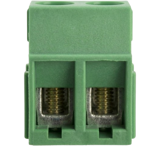
A 2 Point Terminal Block is a type of electrical connector designed to securely connect two wires. It features two terminals, typically used for input and output connections, and provides a reliable, organized, and reusable solution for managing electrical connections. These terminal blocks are widely used in electrical and electronic systems due to their ease of use, durability, and ability to handle a range of voltages and currents.
Explore Projects Built with 2 Point Terminal Block
 Open Project in Cirkit Designer
 Open Project in Cirkit Designer
 Open Project in Cirkit Designer
 Open Project in Cirkit Designer
Explore Projects Built with 2 Point Terminal Block
Open Project in Cirkit DesignerOpen Project in Cirkit DesignerOpen Project in Cirkit DesignerOpen Project in Cirkit DesignerCommon Applications and Use Cases
- Industrial control panels and automation systems
- Power distribution in electrical circuits
- Connecting sensors, actuators, or other devices in prototyping and testing
- Home electrical wiring and DIY electronics projects
- Secure connections in Arduino or microcontroller-based projects
Technical Specifications
Key Technical Details
- Number of Terminals: 2
- Voltage Rating: Typically up to 300V (varies by model)
- Current Rating: Typically up to 15A (varies by model)
- Wire Gauge Compatibility: 12-24 AWG (varies by model)
- Material: Insulating body (e.g., polyamide) with metal contacts (e.g., brass or copper alloy)
- Mounting Style: Screw-type or PCB mount
- Operating Temperature: -40°C to +105°C (varies by model)
Pin Configuration and Descriptions
The 2 Point Terminal Block does not have traditional "pins" like ICs but instead features two screw terminals for wire connections. Below is a description of the terminals:
| Terminal Number | Description |
|---|---|
| 1 | Input terminal for wire connection |
| 2 | Output terminal for wire connection |
Usage Instructions
How to Use the Component in a Circuit
- Prepare the Wires: Strip the insulation from the ends of the wires you want to connect, exposing about 5-7mm of the conductor.
- Insert the Wires: Loosen the screws on the terminal block using a screwdriver. Insert the stripped end of the wire into the terminal opening.
- Secure the Connection: Tighten the screws to clamp the wire securely in place. Ensure the wire is firmly held and does not slip out.
- Connect to the Circuit: Use the terminal block to connect the input and output wires as needed in your circuit.
Important Considerations and Best Practices
- Wire Gauge: Ensure the wire gauge is compatible with the terminal block to avoid loose connections or damage.
- Tightening Screws: Do not overtighten the screws, as this may damage the wire or the terminal block.
- Voltage and Current Ratings: Always check the voltage and current ratings of the terminal block to ensure it is suitable for your application.
- Insulation: Ensure that no exposed wire is left outside the terminal block to prevent short circuits.
- Mounting: If using a PCB-mounted terminal block, solder it securely to the PCB to ensure a stable connection.
Example: Connecting a 2 Point Terminal Block to an Arduino UNO
The 2 Point Terminal Block can be used to connect external devices, such as a motor or LED, to an Arduino UNO. Below is an example of how to use it to control an LED:
Circuit Setup
- Connect one terminal of the block to the Arduino's digital pin (e.g., pin 13).
- Connect the other terminal to the LED's positive lead.
- Connect the LED's negative lead to a resistor, and then to the Arduino's GND pin.
Arduino Code
// Example code to blink an LED connected via a 2 Point Terminal Block
const int ledPin = 13; // Pin connected to the terminal block

void setup() {
  pinMode(ledPin, OUTPUT); // Set the pin as an output
}

void loop() {
  digitalWrite(ledPin, HIGH); // Turn the LED on
  delay(1000);               // Wait for 1 second
  digitalWrite(ledPin, LOW);  // Turn the LED off
  delay(1000);               // Wait for 1 second
}
Troubleshooting and FAQs
Common Issues Users Might Face
- Loose Connections: If the wires are not securely clamped, the connection may be intermittent or fail.
- Solution: Ensure the screws are tightened properly and the wire is fully inserted.
- Overheating: Using the terminal block beyond its current rating can cause overheating.
- Solution: Verify the current rating and ensure it matches your circuit's requirements.
- Wire Slipping Out: If the wire gauge is too small or improperly stripped, it may slip out of the terminal.
- Solution: Use the correct wire gauge and strip the insulation properly.
- Short Circuits: Exposed wire outside the terminal block can cause short circuits.
- Solution: Ensure all exposed wire is fully inside the terminal block.
FAQs
Q: Can I use a 2 Point Terminal Block for high-frequency signals?
A: While terminal blocks are primarily designed for power and low-frequency signals, they can be used for high-frequency signals in some cases. However, ensure the connection is secure and consider potential signal degradation.
Q: Are 2 Point Terminal Blocks reusable?
A: Yes, they are reusable. You can loosen the screws, remove the wires, and use the terminal block in another application.
Q: Can I use stranded wires with a terminal block?
A: Yes, stranded wires can be used. However, it is recommended to use ferrules to prevent fraying and ensure a secure connection.
Q: How do I mount a terminal block on a PCB?
A: For PCB-mounted terminal blocks, solder the pins to the PCB pads, ensuring proper alignment and a strong solder joint.