Cirkit Designer
Your all-in-one circuit design IDE
Home /
Component Documentation
How to Use 3PDT Foot Switch: Examples, Pinouts, and Specs

Introduction
- The 3PDT (Triple Pole Double Throw) foot switch is a mechanical switch designed to control three independent circuits simultaneously. It features a robust, foot-operated mechanism, making it ideal for applications where hands-free operation is required.
- Commonly used in guitar pedals, audio equipment, and other electronic devices, the 3PDT foot switch is essential for toggling effects, bypassing circuits, or switching between different signal paths.
Explore Projects Built with 3PDT Foot Switch
Dual Motor Control System with DPDT Switches and Planetary Gearbox Motors

This circuit features two DPDT switches that control the direction of two MRB Planetary gearbox motors. The switches are connected to a connector, allowing for external control inputs to change the motor directions.
Toggle Switch Controlled Lamp Circuit with Banana Sockets

This circuit consists of two toggle switches and a red lamp connected to panel mount banana sockets. The switches control the connection between the red and black banana sockets, allowing the lamp to be turned on or off depending on the switch positions.
9V Battery-Powered DC Motor with Toggle Switch Control
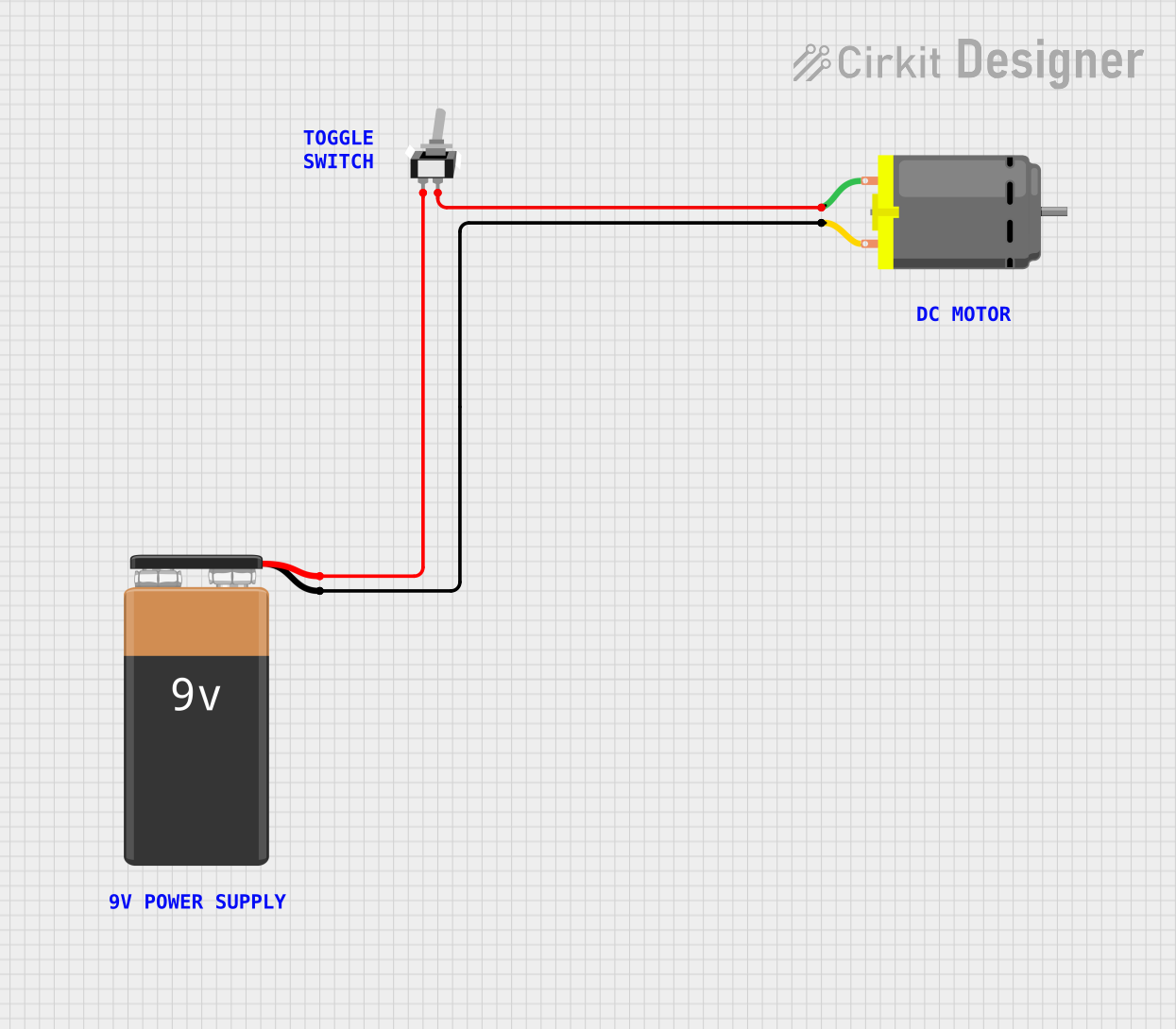
This circuit is designed to control a DC motor using a single-pole single-throw (SPST) toggle switch. The 9V battery provides power to the motor, and the toggle switch acts as an on/off control to allow or interrupt the current flow to the motor.
Battery-Powered DPDT Switch Controlled Motor System
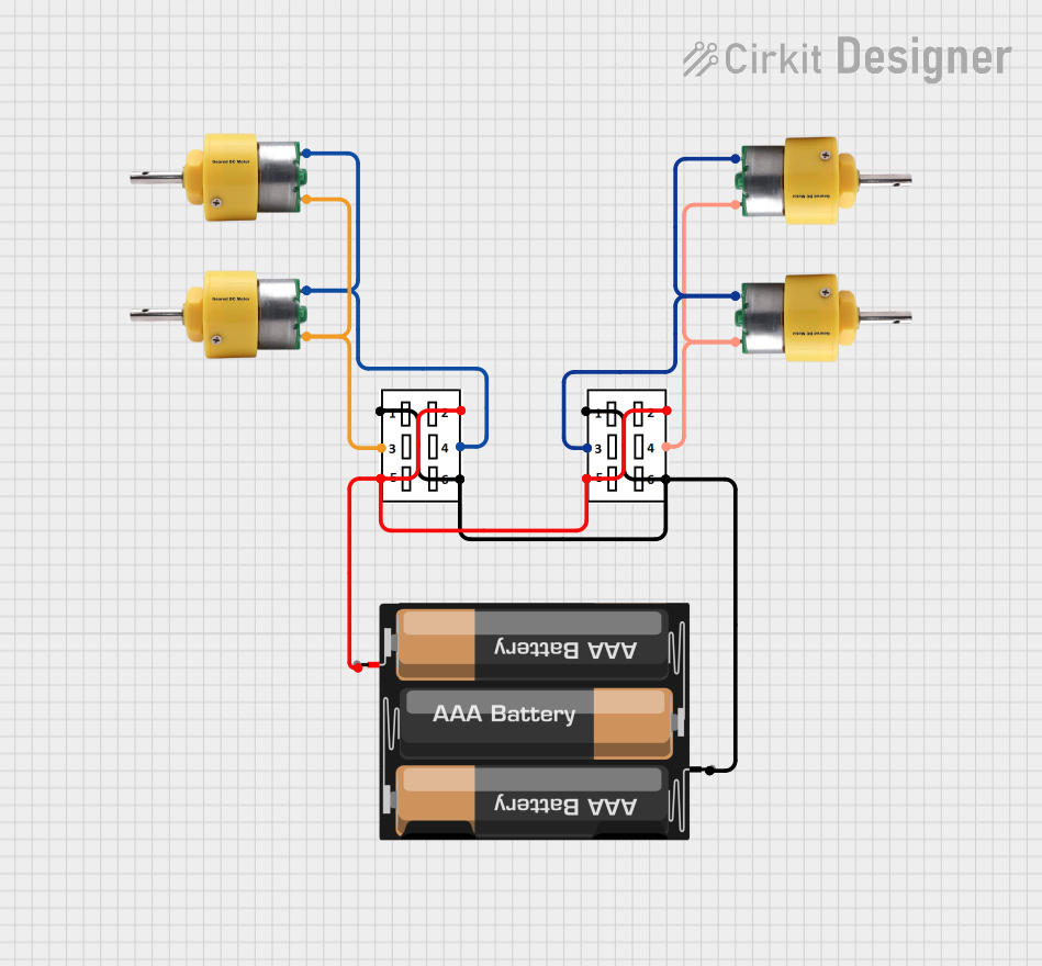
This circuit uses two DPDT switches to control the direction of four center shaft metal geared motors powered by a 3xAA battery pack. The switches allow for reversing the polarity of the motors, enabling forward and reverse motion.
Explore Projects Built with 3PDT Foot Switch
Dual Motor Control System with DPDT Switches and Planetary Gearbox Motors
This circuit features two DPDT switches that control the direction of two MRB Planetary gearbox motors. The switches are connected to a connector, allowing for external control inputs to change the motor directions.
Toggle Switch Controlled Lamp Circuit with Banana Sockets
This circuit consists of two toggle switches and a red lamp connected to panel mount banana sockets. The switches control the connection between the red and black banana sockets, allowing the lamp to be turned on or off depending on the switch positions.
9V Battery-Powered DC Motor with Toggle Switch Control
This circuit is designed to control a DC motor using a single-pole single-throw (SPST) toggle switch. The 9V battery provides power to the motor, and the toggle switch acts as an on/off control to allow or interrupt the current flow to the motor.
Battery-Powered DPDT Switch Controlled Motor System
This circuit uses two DPDT switches to control the direction of four center shaft metal geared motors powered by a 3xAA battery pack. The switches allow for reversing the polarity of the motors, enabling forward and reverse motion.
Technical Specifications
- Switch Type: Triple Pole Double Throw (3PDT)
- Operation: Latching (maintains state after actuation)
- Contact Rating: Typically 2A at 250VAC or 4A at 30VDC (check specific model for exact ratings)
- Number of Terminals: 9 (3 poles, each with a common, normally open, and normally closed terminal)
- Actuation Force: ~1.5-2.5 kgf (varies by manufacturer)
- Mechanical Life: Up to 30,000 actuations (varies by manufacturer)
- Mounting Style: Panel mount with threaded bushing
- Dimensions: Typically 12mm x 12mm x 40mm (varies by model)
Pin Configuration and Descriptions
The 3PDT foot switch has 9 terminals arranged in a 3x3 grid. Each row corresponds to one pole, and each column represents the common (C), normally closed (NC), and normally open (NO) terminals.
| Pin Number | Label | Description |
|---|---|---|
| 1 | NC1 | Normally Closed terminal for Pole 1 (connected to C1 when switch is OFF) |
| 2 | C1 | Common terminal for Pole 1 |
| 3 | NO1 | Normally Open terminal for Pole 1 (connected to C1 when switch is ON) |
| 4 | NC2 | Normally Closed terminal for Pole 2 (connected to C2 when switch is OFF) |
| 5 | C2 | Common terminal for Pole 2 |
| 6 | NO2 | Normally Open terminal for Pole 2 (connected to C2 when switch is ON) |
| 7 | NC3 | Normally Closed terminal for Pole 3 (connected to C3 when switch is OFF) |
| 8 | C3 | Common terminal for Pole 3 |
| 9 | NO3 | Normally Open terminal for Pole 3 (connected to C3 when switch is ON) |
Usage Instructions
How to Use the 3PDT Foot Switch in a Circuit
- Identify the Terminals: Refer to the pin configuration table above to identify the NC, NO, and C terminals for each pole.
- Wiring:
- Connect the C terminals to the input signals or power sources.
- Use the NO terminals for the active state (when the switch is pressed).
- Use the NC terminals for the default state (when the switch is not pressed).
- Mounting:
- Drill a hole in the enclosure to fit the threaded bushing of the switch.
- Secure the switch using the provided nut and washer.
- Soldering:
- Use a soldering iron with a fine tip to connect wires to the terminals.
- Avoid excessive heat to prevent damage to the switch.
Example: Using a 3PDT Foot Switch in a Guitar Pedal
The 3PDT foot switch is commonly used to toggle between true bypass and an active effect in guitar pedals. Below is an example of how to wire the switch for this purpose:
- Pole 1: Controls the LED indicator (ON when the effect is active).
- Pole 2: Switches the audio signal between the effect circuit and bypass.
- Pole 3: Grounds the input of the effect circuit when bypassed to prevent noise.
Arduino Example: Reading the State of a 3PDT Switch
While the 3PDT switch is typically used in analog circuits, you can also interface it with a microcontroller like the Arduino to read its state.
// Arduino code to read the state of a 3PDT switch
// Connect the common terminal (C1) to GND and the NO1 terminal to pin 2.

const int switchPin = 2; // Pin connected to NO1 terminal of the 3PDT switch
int switchState = 0;     // Variable to store the switch state

void setup() {
  pinMode(switchPin, INPUT_PULLUP); // Enable internal pull-up resistor
  Serial.begin(9600);              // Initialize serial communication
}

void loop() {
  switchState = digitalRead(switchPin); // Read the state of the switch

  if (switchState == LOW) {
    // Switch is pressed (NO1 connected to C1)
    Serial.println("Switch is ON");
  } else {
    // Switch is not pressed (NC1 connected to C1)
    Serial.println("Switch is OFF");
  }

  delay(100); // Small delay to debounce the switch
}
Important Considerations and Best Practices
- Debouncing: Mechanical switches like the 3PDT can produce noise or "bouncing" when toggled. Use a debounce circuit or software debounce logic to ensure stable operation.
- Current Rating: Ensure the connected load does not exceed the switch's current rating to avoid damage.
- Mounting: Secure the switch firmly to prevent movement during operation, especially in foot-operated applications.
- Heat Management: Avoid prolonged exposure to high temperatures during soldering to prevent damage to the internal contacts.
Troubleshooting and FAQs
Common Issues
- Switch Not Working:
- Check for loose or incorrect connections.
- Verify that the switch is not damaged or worn out.
- Noise or Interference:
- Ensure proper grounding of the circuit.
- Use shielded cables for audio applications.
- LED Indicator Not Lighting:
- Verify the polarity of the LED and the resistor value.
- Check the wiring of the LED circuit.
Solutions and Tips for Troubleshooting
- Use a multimeter to test continuity between the terminals to confirm proper operation.
- If the switch feels "sticky" or unresponsive, inspect for physical damage or debris.
- For audio applications, ensure the switch is wired correctly to avoid signal loss or distortion.
By following this documentation, you can effectively integrate and troubleshoot the 3PDT foot switch in your projects.