How to Use SCC PWM: Examples, Pinouts, and Specs
Introduction
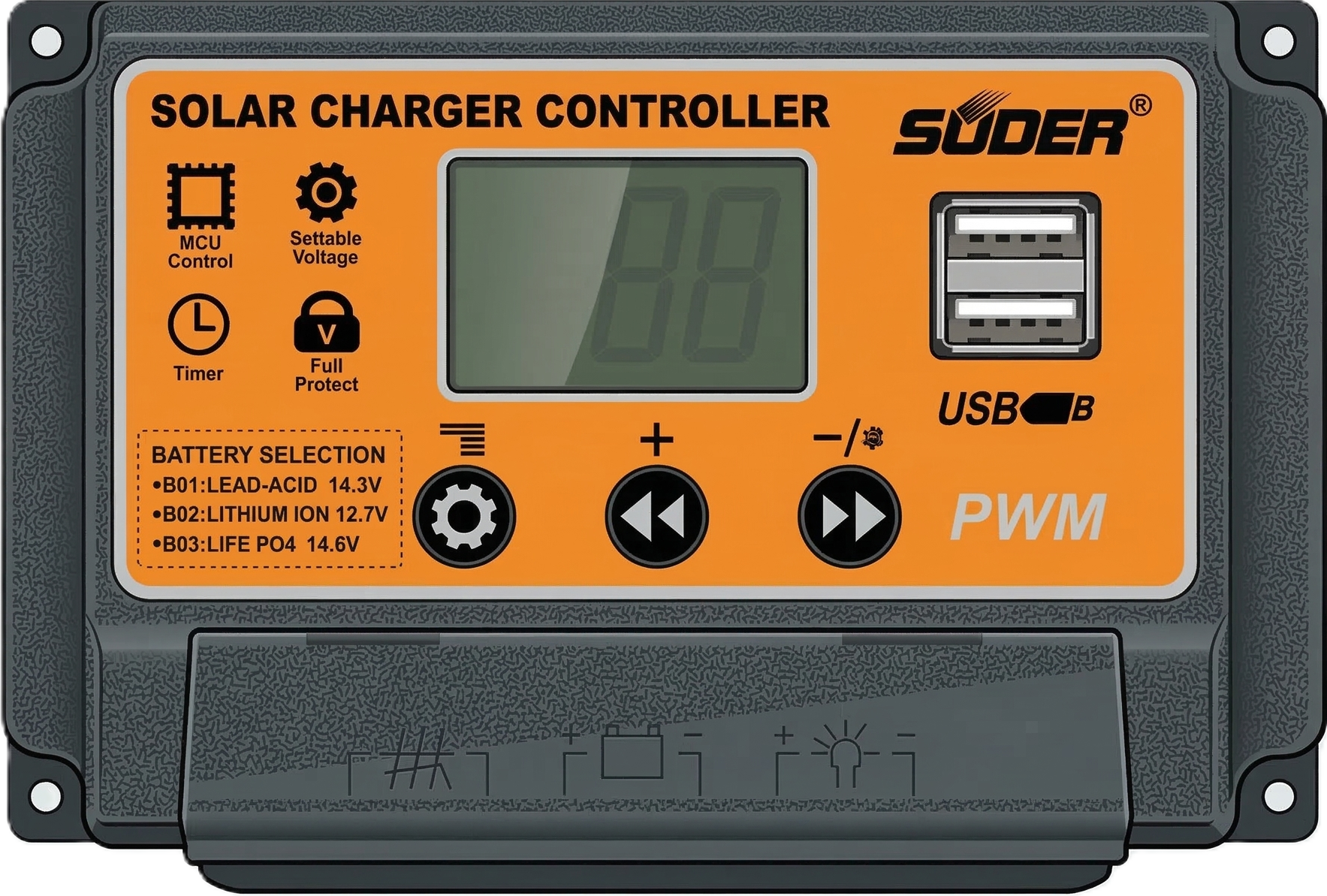
The SCC PWM (Switching Control Circuit Pulse Width Modulator) by Suoer is a versatile electronic component designed to control the power delivered to electrical devices. It achieves this by varying the width of the pulses in a pulse train, enabling efficient energy management. This component is widely used in applications such as motor speed control, LED dimming, and power supply regulation.
Explore Projects Built with SCC PWM


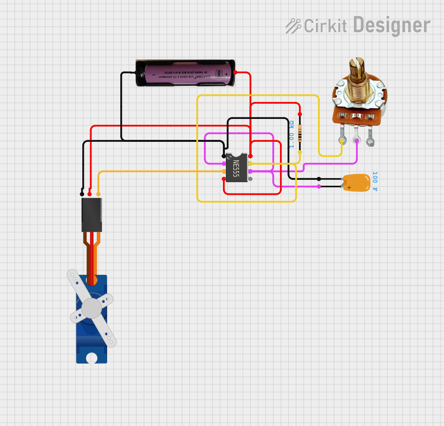
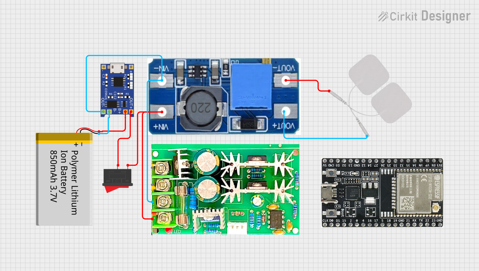
Explore Projects Built with SCC PWM
Common Applications and Use Cases
- Motor Control: Adjusting the speed of DC motors in industrial and consumer applications.
- LED Dimming: Controlling the brightness of LEDs in lighting systems.
- Power Supplies: Regulating voltage and current in switching power supplies.
- Battery Chargers: Managing charging cycles for batteries efficiently.
- Heating Elements: Controlling the power delivered to resistive heating elements.
Technical Specifications
The SCC PWM is designed to operate efficiently in a variety of electronic systems. Below are its key technical details:
Key Technical Details
| Parameter | Value |
|---|---|
| Input Voltage Range | 5V to 24V |
| Output Voltage Range | 0V to Input Voltage |
| Output Current | Up to 10A |
| PWM Frequency | 1 kHz to 20 kHz (adjustable) |
| Duty Cycle Range | 0% to 100% |
| Efficiency | >90% |
| Operating Temperature | -20°C to 85°C |
| Dimensions | 50mm x 30mm x 15mm |
Pin Configuration and Descriptions
The SCC PWM typically features a simple pinout for easy integration into circuits. Below is the pin configuration:
| Pin Number | Pin Name | Description |
|---|---|---|
| 1 | VIN | Positive input voltage terminal (5V to 24V). |
| 2 | GND | Ground terminal for the input and output. |
| 3 | VOUT | Positive output voltage terminal (0V to VIN, PWM controlled). |
| 4 | PWM Control | Input for external PWM signal (optional). |
| 5 | Enable | Enable/disable the output (logic HIGH to enable). |
Usage Instructions
The SCC PWM is straightforward to use in a variety of circuits. Follow the steps below to integrate it into your project:
How to Use the SCC PWM in a Circuit
- Power Supply Connection: Connect the input voltage (VIN) to a DC power source within the specified range (5V to 24V). Ensure the power source can supply sufficient current for your load.
- Load Connection: Connect the load (e.g., motor, LED, or heating element) between the VOUT and GND pins.
- PWM Adjustment:
- If the SCC PWM has an onboard potentiometer, adjust it to set the desired duty cycle.
- Alternatively, provide an external PWM signal to the PWM Control pin to control the output.
- Enable the Output: Set the Enable pin to logic HIGH to activate the output. If this pin is left unconnected, the output may remain disabled.
- Test the Circuit: Verify the output voltage and current using a multimeter to ensure proper operation.
Important Considerations and Best Practices
- Heat Dissipation: For high-current applications, ensure adequate heat dissipation using a heatsink or active cooling.
- Input Voltage: Do not exceed the maximum input voltage of 24V to avoid damaging the component.
- PWM Frequency: Select an appropriate PWM frequency for your application. For motor control, a frequency between 1 kHz and 10 kHz is typically suitable.
- External PWM Signal: If using an external PWM signal, ensure it is within the supported frequency range (1 kHz to 20 kHz) and has a logic level compatible with the SCC PWM.
Example: Using SCC PWM with Arduino UNO
The SCC PWM can be controlled using an Arduino UNO to generate a PWM signal. Below is an example code snippet:
// Example: Controlling SCC PWM with Arduino UNO
// This code generates a PWM signal on pin 9 to control the SCC PWM module.

const int pwmPin = 9; // PWM output pin connected to SCC PWM's PWM Control pin
int dutyCycle = 128;  // Duty cycle (0-255, where 255 = 100%)

void setup() {
  pinMode(pwmPin, OUTPUT); // Set the PWM pin as an output
}

void loop() {
  analogWrite(pwmPin, dutyCycle); // Generate PWM signal with specified duty cycle
  delay(1000); // Wait for 1 second
  dutyCycle = (dutyCycle + 64) % 256; // Increment duty cycle (wraps around at 255)
}
Note: Adjust the
dutyCyclevariable to control the output power. A value of 0 corresponds to 0% duty cycle, and 255 corresponds to 100%.
Troubleshooting and FAQs
Common Issues and Solutions
No Output Voltage:
- Ensure the Enable pin is set to logic HIGH.
- Verify the input voltage is within the specified range (5V to 24V).
- Check all connections for proper wiring.
Overheating:
- Ensure the load current does not exceed the maximum rating of 10A.
- Use a heatsink or active cooling for high-power applications.
Unstable Output:
- Verify the PWM frequency is within the supported range (1 kHz to 20 kHz).
- Check for noise or interference in the external PWM signal.
Load Not Responding:
- Confirm the load is functional and properly connected.
- Check the duty cycle setting and adjust as needed.
FAQs
Q: Can I use the SCC PWM with an AC load?
A: No, the SCC PWM is designed for DC loads only. Using it with an AC load may damage the component.
Q: What happens if I exceed the input voltage range?
A: Exceeding the input voltage range (24V) can permanently damage the SCC PWM. Always use a regulated power supply.
Q: Can I control multiple loads with one SCC PWM?
A: Yes, as long as the total current does not exceed the maximum rating of 10A.
Q: Is the SCC PWM compatible with 3.3V logic?
A: Yes, the PWM Control and Enable pins are typically compatible with both 3.3V and 5V logic levels.
By following this documentation, you can effectively integrate and troubleshoot the SCC PWM in your projects.