
How to Use Adafruit Mini Analog Thumbstick: Examples, Pinouts, and Specs
 Design with Adafruit Mini Analog Thumbstick in Cirkit Designer
Introduction
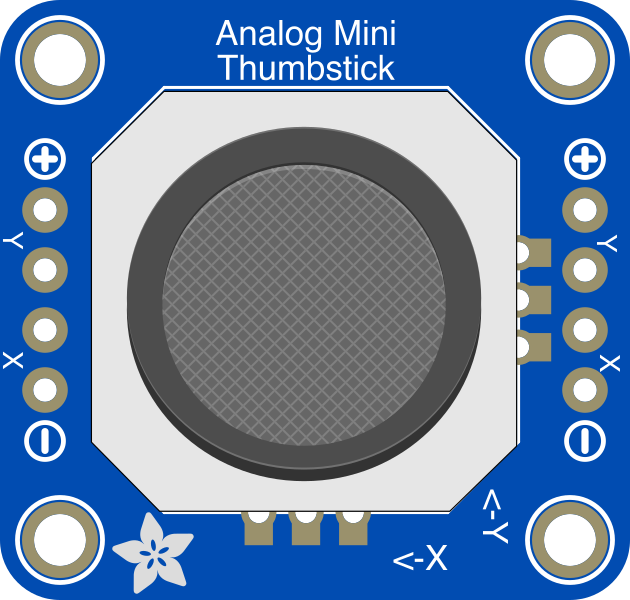
The Adafruit Mini Analog Thumbstick (Part ID: 3246) is a compact joystick module designed to provide precise analog input for a variety of applications. It features two axes of movement (X and Y) and an integrated push-button switch, making it ideal for controlling devices such as robots, gaming systems, and interactive projects. Its small size and versatility make it a popular choice for hobbyists and professionals alike.
Explore Projects Built with Adafruit Mini Analog Thumbstick
 Open Project in Cirkit Designer
 Open Project in Cirkit Designer
 Open Project in Cirkit Designer
 Open Project in Cirkit Designer
Explore Projects Built with Adafruit Mini Analog Thumbstick
Open Project in Cirkit DesignerOpen Project in Cirkit DesignerOpen Project in Cirkit DesignerOpen Project in Cirkit DesignerCommon Applications
- Robotics control systems
- Gaming controllers and arcade machines
- User interface navigation
- DIY electronics projects
- Remote-controlled devices
Technical Specifications
The Adafruit Mini Analog Thumbstick is designed for ease of use and compatibility with microcontrollers like Arduino. Below are its key technical details:
Key Specifications
| Parameter | Value |
|---|---|
| Manufacturer | Adafruit |
| Part ID | 3246 |
| Operating Voltage | 3.3V to 5V |
| Output Type | Analog (X and Y axes), Digital (button) |
| X/Y Axis Resistance | 10 kΩ potentiometers |
| Push-Button Type | Momentary switch |
| Dimensions | 26mm x 26mm x 20mm |
| Weight | 6g |
Pin Configuration
The module has 5 pins for interfacing with a microcontroller. The table below describes each pin:
| Pin Name | Description |
|---|---|
| VCC | Power supply input (3.3V to 5V) |
| GND | Ground |
| VRx | Analog output for the X-axis |
| VRy | Analog output for the Y-axis |
| SW | Digital output for the push-button (active LOW) |
Usage Instructions
Connecting the Thumbstick
To use the Adafruit Mini Analog Thumbstick in a circuit, follow these steps:
- Power the module: Connect the
VCCpin to a 3.3V or 5V power source and theGNDpin to ground. - Connect the analog outputs: Connect the
VRxandVRypins to analog input pins on your microcontroller (e.g., Arduino). - Connect the push-button: Connect the
SWpin to a digital input pin on your microcontroller. Use a pull-up resistor if necessary, as the button output is active LOW.
Example Circuit with Arduino UNO
Below is an example of how to connect the thumbstick to an Arduino UNO:
VCC→ 5VGND→ GNDVRx→ A0VRy→ A1SW→ D2
Example Arduino Code
The following Arduino sketch reads the X and Y axis values and detects button presses:
// Pin definitions
const int VRxPin = A0; // X-axis analog input
const int VRyPin = A1; // Y-axis analog input
const int SWPin = 2;   // Push-button digital input

void setup() {
  // Initialize serial communication for debugging
  Serial.begin(9600);

  // Configure the push-button pin as input with internal pull-up
  pinMode(SWPin, INPUT_PULLUP);
}

void loop() {
  // Read the X and Y axis values (0 to 1023)
  int xValue = analogRead(VRxPin);
  int yValue = analogRead(VRyPin);

  // Read the push-button state (LOW when pressed)
  bool buttonPressed = (digitalRead(SWPin) == LOW);

  // Print the values to the Serial Monitor
  Serial.print("X: ");
  Serial.print(xValue);
  Serial.print(" | Y: ");
  Serial.print(yValue);
  Serial.print(" | Button: ");
  Serial.println(buttonPressed ? "Pressed" : "Released");

  // Add a small delay for stability
  delay(100);
}
Best Practices
- Use a stable power supply to ensure consistent readings.
- Avoid applying excessive force to the joystick to prevent damage.
- Use proper pull-up or pull-down resistors for the push-button if not using the internal pull-up feature of your microcontroller.
Troubleshooting and FAQs
Common Issues and Solutions
Joystick readings are unstable or noisy:
- Ensure the power supply is stable and free of noise.
- Add a small capacitor (e.g., 0.1 µF) between the
VRx/VRypins and ground to filter noise.
Push-button does not register presses:
- Verify the
SWpin is connected to the correct digital input pin. - Check if the internal pull-up resistor is enabled or add an external pull-up resistor.
- Verify the
Joystick does not respond:
- Double-check all connections, especially
VCCandGND. - Ensure the microcontroller's analog pins are functioning correctly.
- Double-check all connections, especially
Readings are inverted:
- If the X or Y axis values are inverted, reverse the connections to the analog pins in your code.
FAQs
Q: Can I use this joystick with a Raspberry Pi?
A: Yes, the joystick can be used with a Raspberry Pi. Connect the analog outputs (VRx and VRy) to an ADC (Analog-to-Digital Converter) module, as the Raspberry Pi does not have built-in analog input pins.
Q: What is the range of the analog output values?
A: The analog output values range from 0 to 1023 when using a 10-bit ADC, such as the one on an Arduino UNO.
Q: Is the joystick compatible with 3.3V systems?
A: Yes, the joystick operates at both 3.3V and 5V, making it compatible with a wide range of microcontrollers.
Q: Can I replace the push-button?
A: The push-button is integrated into the module and cannot be replaced without significant modification.