
How to Use 2.4GHz ANT IC: Examples, Pinouts, and Specs

 Design with 2.4GHz ANT IC in Cirkit Designer
Introduction
The 2.4GHz antenna integrated circuit (IC) is a specialized component designed for wireless communication applications. It operates at the 2.4GHz frequency, a widely used band for technologies such as Wi-Fi, Bluetooth, Zigbee, and other short-range wireless protocols. This IC integrates the antenna functionality into a compact design, optimizing signal transmission and reception while reducing the need for external antenna components.
Explore Projects Built with 2.4GHz ANT IC
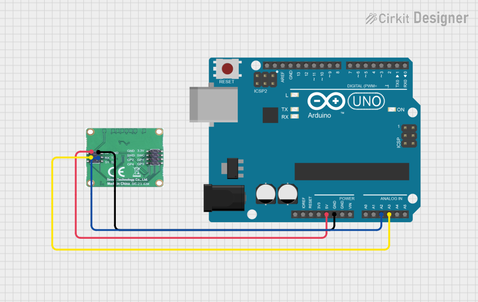 Open Project in Cirkit Designer
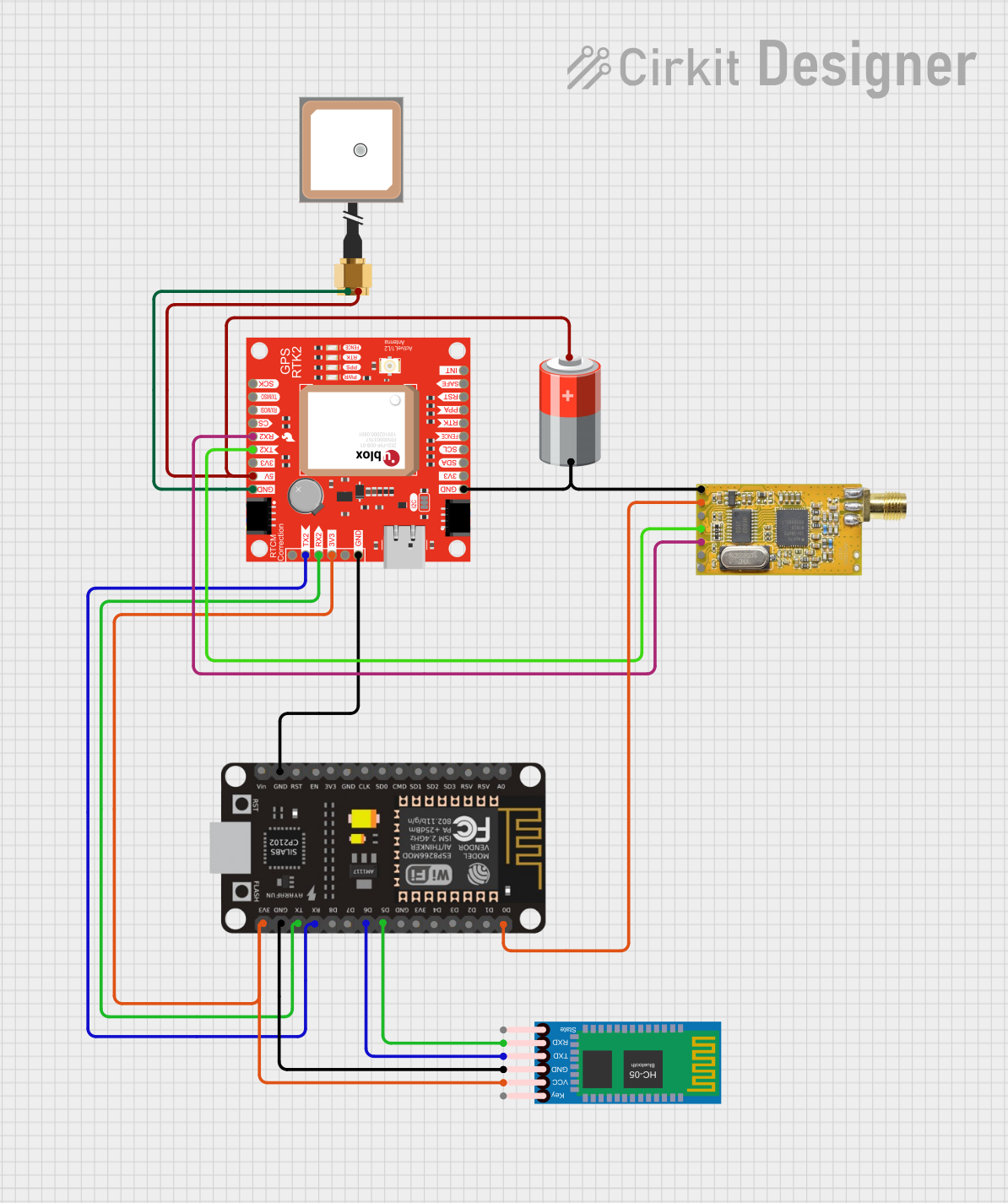 Open Project in Cirkit Designer
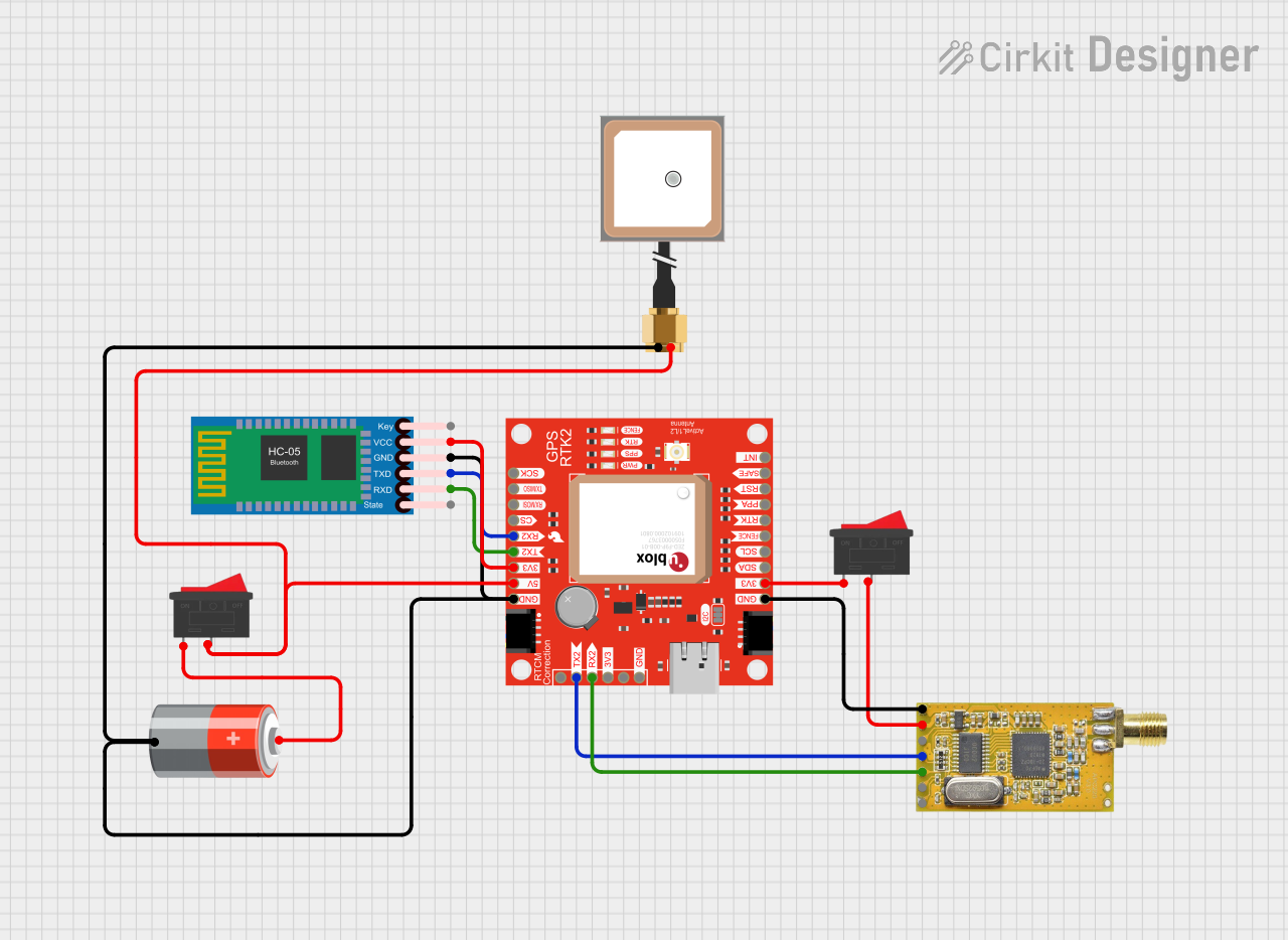 Open Project in Cirkit Designer
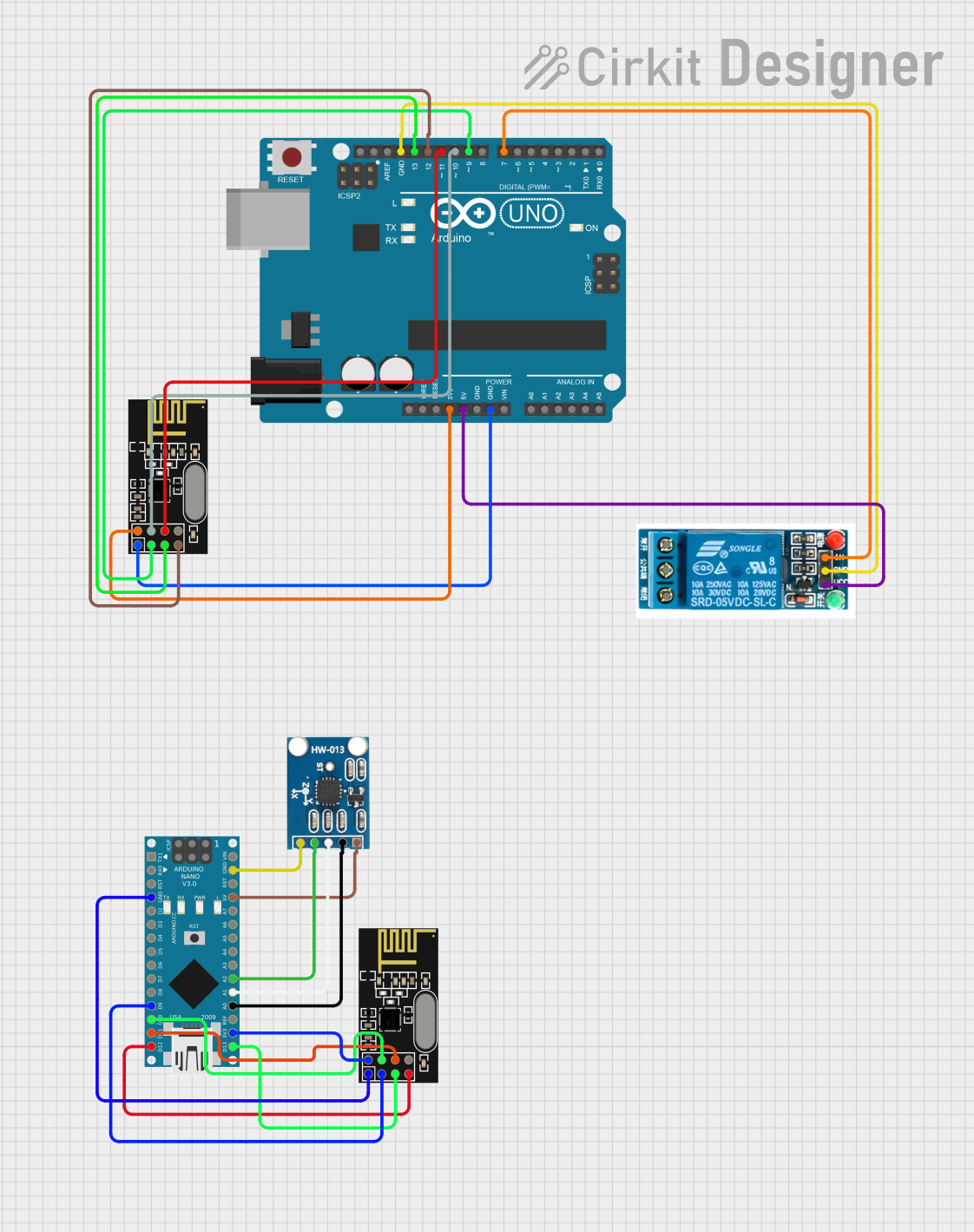 Open Project in Cirkit Designer
Explore Projects Built with 2.4GHz ANT IC
Open Project in Cirkit DesignerOpen Project in Cirkit DesignerOpen Project in Cirkit DesignerOpen Project in Cirkit DesignerCommon Applications and Use Cases
- Wi-Fi Modules: Enhances wireless connectivity in IoT devices, routers, and access points.
- Bluetooth Devices: Used in headphones, speakers, and wearable devices for seamless communication.
- Zigbee Networks: Ideal for smart home devices, such as lighting systems and sensors.
- Wireless Peripherals: Keyboards, mice, and game controllers.
- Industrial IoT: Enables robust communication in factory automation and monitoring systems.
Technical Specifications
The following table outlines the key technical details of the 2.4GHz ANT IC:
| Parameter | Value |
|---|---|
| Operating Frequency | 2.4GHz |
| Input Voltage Range | 1.8V to 3.6V |
| Current Consumption | 10mA (typical) |
| Output Power | Up to +20 dBm |
| Sensitivity | -95 dBm |
| Impedance | 50Ω |
| Operating Temperature | -40°C to +85°C |
| Package Type | QFN, LGA, or custom compact form |
Pin Configuration and Descriptions
Below is a typical pinout configuration for a 2.4GHz ANT IC. Note that the exact pinout may vary depending on the manufacturer.
| Pin Number | Pin Name | Description |
|---|---|---|
| 1 | VCC | Power supply input (1.8V to 3.6V). |
| 2 | GND | Ground connection. |
| 3 | RF_IN | Radio frequency input for signal reception. |
| 4 | RF_OUT | Radio frequency output for signal transmission. |
| 5 | CTRL | Control pin for enabling/disabling the IC. |
| 6 | NC | No connection (leave unconnected). |
Usage Instructions
How to Use the Component in a Circuit
- Power Supply: Connect the VCC pin to a stable power source within the specified voltage range (1.8V to 3.6V). Ensure proper decoupling capacitors are placed near the VCC pin to minimize noise.
- Grounding: Connect the GND pin to the circuit ground. A solid ground plane is recommended for optimal performance.
- RF Connections:
- Connect the RF_IN pin to the signal source (e.g., a transceiver module).
- Connect the RF_OUT pin to the antenna or matching network.
- Control Pin: Use the CTRL pin to enable or disable the IC. Pull the pin high to enable the IC and low to disable it.
- Impedance Matching: Ensure a 50Ω impedance matching network is used for RF_IN and RF_OUT to maximize signal integrity.
Important Considerations and Best Practices
- PCB Design: Use a high-frequency PCB layout with minimal trace lengths for RF signals. Avoid sharp bends in RF traces.
- Decoupling: Place decoupling capacitors close to the VCC pin to filter out noise.
- Antenna Placement: Position the antenna away from metal objects and other components to reduce interference.
- Thermal Management: Ensure adequate heat dissipation, especially in high-power applications.
Example: Connecting to an Arduino UNO
The 2.4GHz ANT IC can be used with an Arduino UNO for wireless communication. Below is an example of interfacing the IC with an Arduino UNO for a basic Bluetooth application:
// Example: Using a 2.4GHz ANT IC with Arduino UNO for Bluetooth communication

#include <SoftwareSerial.h>

// Define RX and TX pins for Bluetooth communication
SoftwareSerial bluetooth(10, 11); // RX = Pin 10, TX = Pin 11

void setup() {
  // Initialize serial communication for debugging
  Serial.begin(9600);
  Serial.println("2.4GHz ANT IC Bluetooth Example");

  // Initialize Bluetooth communication
  bluetooth.begin(9600);
  bluetooth.println("Hello from Arduino!");
}

void loop() {
  // Check if data is available from Bluetooth
  if (bluetooth.available()) {
    char data = bluetooth.read();
    Serial.print("Received: ");
    Serial.println(data);
  }

  // Send data to Bluetooth
  bluetooth.println("Arduino says hi!");
  delay(1000); // Wait for 1 second
}
Troubleshooting and FAQs
Common Issues and Solutions
No Signal Transmission or Reception
- Cause: Incorrect power supply or loose connections.
- Solution: Verify the VCC and GND connections. Ensure the power supply is within the specified range.
Poor Signal Quality
- Cause: Improper impedance matching or antenna placement.
- Solution: Check the impedance matching network and ensure the antenna is positioned correctly.
Overheating
- Cause: Excessive power or inadequate heat dissipation.
- Solution: Reduce the output power or improve thermal management.
Interference with Other Devices
- Cause: Operating in a crowded 2.4GHz band.
- Solution: Use frequency-hopping or channel selection features to avoid interference.
FAQs
Q: Can the 2.4GHz ANT IC be used for long-range communication?
A: The IC is optimized for short to medium-range communication. For long-range applications, consider using external amplifiers or directional antennas.
Q: Is the IC compatible with 5V systems?
A: No, the IC operates within a voltage range of 1.8V to 3.6V. Use a voltage regulator or level shifter for 5V systems.
Q: How do I test the IC's performance?
A: Use a spectrum analyzer or network analyzer to measure signal strength, frequency response, and impedance matching.
Q: Can I use this IC with other wireless protocols?
A: Yes, the IC supports various 2.4GHz protocols, including Wi-Fi, Bluetooth, and Zigbee, depending on the transceiver module used.