How to Use 7447: Examples, Pinouts, and Specs
Introduction
The IC 7447 is a BCD (Binary-Coded Decimal) to 7-segment decoder/driver manufactured by IC. It is designed to convert a 4-bit BCD input into the corresponding outputs required to drive a 7-segment display. This component simplifies the process of displaying decimal numbers on 7-segment displays by handling the decoding internally.
Explore Projects Built with 7447

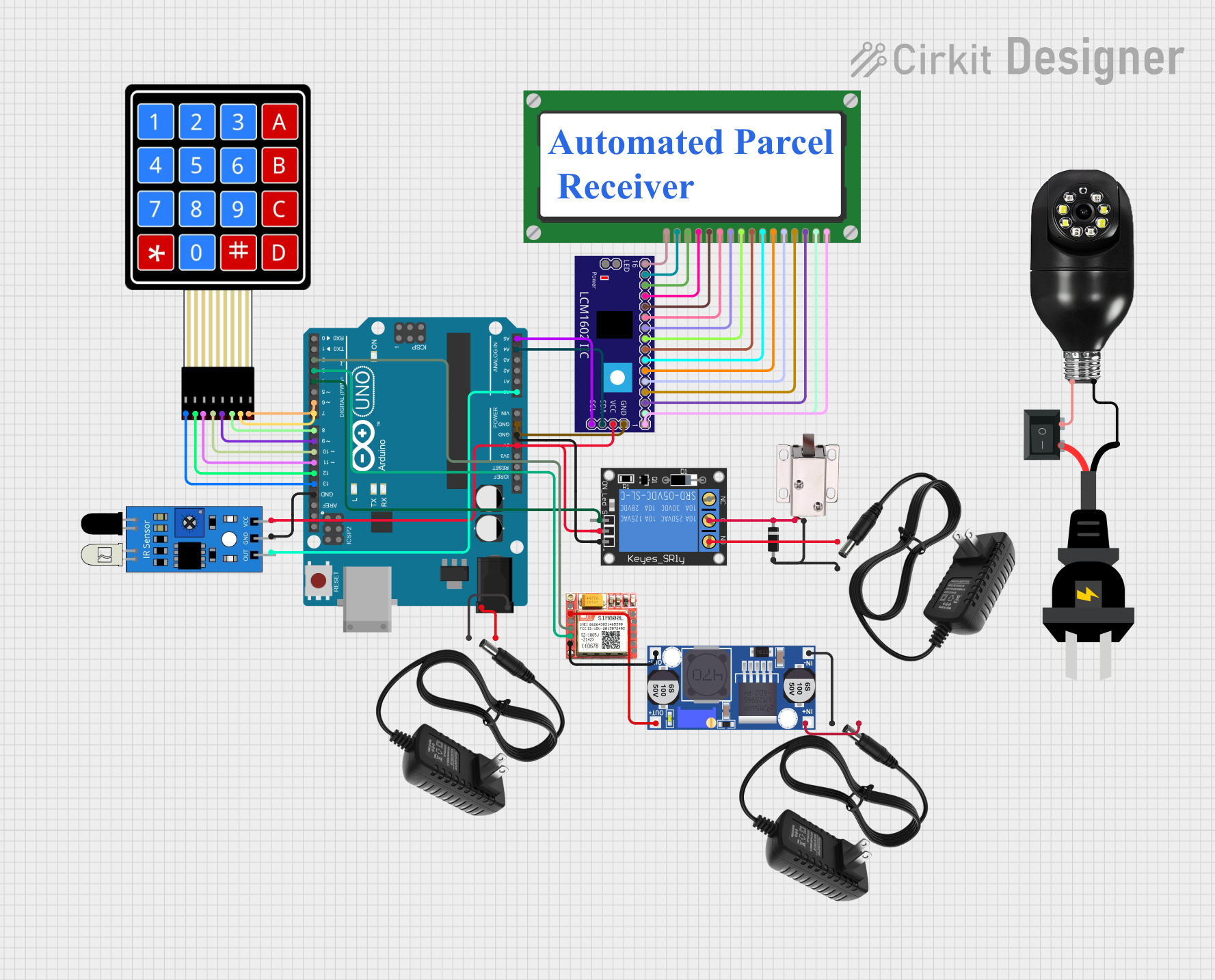

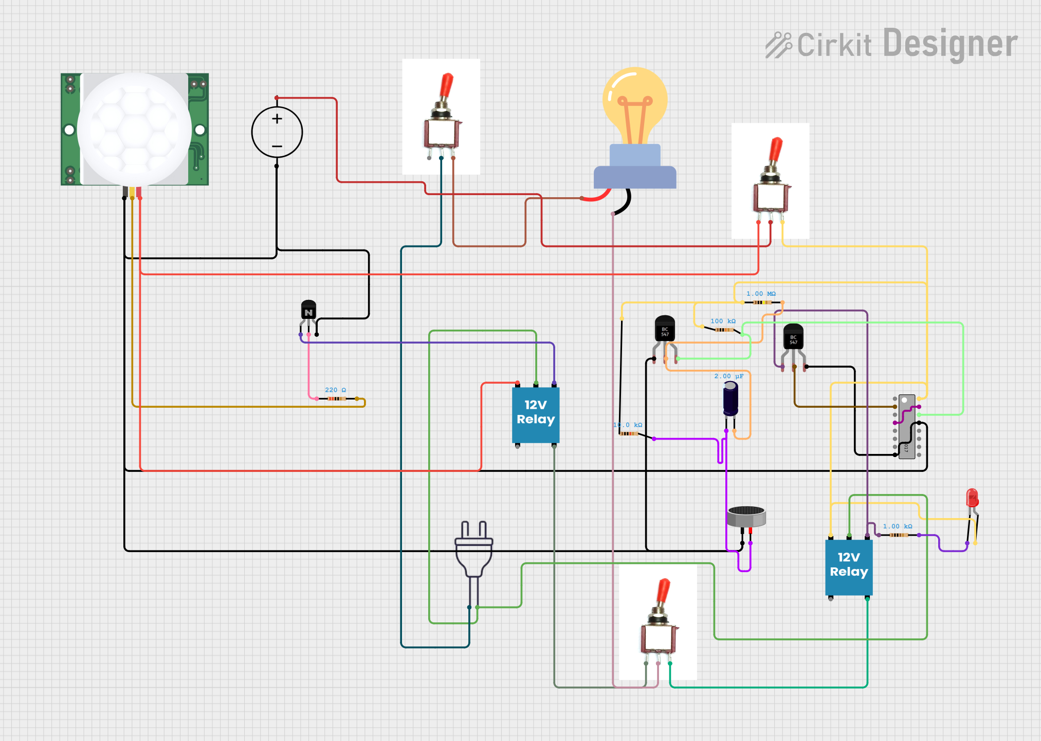
Explore Projects Built with 7447
Common Applications and Use Cases
- Digital clocks and timers
- Electronic counters
- Scoreboards
- Simple numeric displays in embedded systems
- Educational projects involving 7-segment displays
Technical Specifications
The following are the key technical details of the IC 7447:
| Parameter | Value |
|---|---|
| Supply Voltage (Vcc) | 4.75V to 5.25V |
| Input Voltage | 0V (Low) to 5V (High) |
| Output Voltage | 0V (Low) to 5V (High) |
| Maximum Output Current | 40 mA per segment |
| Power Dissipation | 500 mW |
| Operating Temperature | 0°C to 70°C |
| Package Type | DIP-16 (Dual Inline Package, 16 pins) |
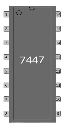
Pin Configuration and Descriptions
The IC 7447 has 16 pins, as described in the table below:
| Pin Number | Pin Name | Description |
|---|---|---|
| 1 | A | BCD Input (Least Significant Bit - LSB) |
| 2 | B | BCD Input |
| 3 | C | BCD Input |
| 4 | D | BCD Input (Most Significant Bit - MSB) |
| 5 | RBI | Ripple Blanking Input (used for blanking leading zeros) |
| 6 | LT | Lamp Test Input (activates all segments for testing when LOW) |
| 7 | BI | Blanking Input (disables all segments when LOW) |
| 8 | GND | Ground (0V reference) |
| 9 | a | Output for segment "a" of the 7-segment display |
| 10 | b | Output for segment "b" of the 7-segment display |
| 11 | c | Output for segment "c" of the 7-segment display |
| 12 | d | Output for segment "d" of the 7-segment display |
| 13 | e | Output for segment "e" of the 7-segment display |
| 14 | f | Output for segment "f" of the 7-segment display |
| 15 | g | Output for segment "g" of the 7-segment display |
| 16 | Vcc | Positive Supply Voltage (4.75V to 5.25V) |
Usage Instructions
How to Use the IC 7447 in a Circuit
- Power Supply: Connect pin 16 (Vcc) to a 5V power supply and pin 8 (GND) to ground.
- BCD Inputs: Connect the 4-bit BCD input (pins 1, 2, 3, and 4) to the binary-coded decimal source, such as a microcontroller or counter IC.
- 7-Segment Display: Connect the output pins (9 to 15) to the corresponding segments (a to g) of a common-anode 7-segment display. Ensure that current-limiting resistors (typically 330Ω to 470Ω) are placed in series with each segment to prevent damage.
- Control Pins:
- RBI (Pin 5): Connect to HIGH if ripple blanking is not required.
- LT (Pin 6): Connect to HIGH during normal operation. Pull LOW to test all segments.
- BI (Pin 7): Connect to HIGH during normal operation. Pull LOW to blank all segments.
Important Considerations and Best Practices
- The IC 7447 is designed for common-anode 7-segment displays. It will not work with common-cathode displays.
- Always use current-limiting resistors to protect the 7-segment display from excessive current.
- Ensure that the BCD input values are within the range of 0 to 9. Inputs outside this range will result in undefined outputs.
- Avoid exceeding the maximum power dissipation and current ratings to prevent damage to the IC.
Example: Connecting the IC 7447 to an Arduino UNO
Below is an example of how to connect the IC 7447 to an Arduino UNO to display numbers on a 7-segment display.
Circuit Connections
- Connect the Arduino digital pins (e.g., D2 to D5) to the BCD input pins (A, B, C, D) of the IC 7447.
- Connect the output pins (a to g) of the IC 7447 to the corresponding segments of the 7-segment display.
- Use 330Ω resistors in series with each segment.
- Connect the common anode of the 7-segment display to 5V.
Arduino Code
// Define the BCD input pins connected to the Arduino
const int bcdPins[4] = {2, 3, 4, 5}; // A, B, C, D

void setup() {
  // Set BCD pins as outputs
  for (int i = 0; i < 4; i++) {
    pinMode(bcdPins[i], OUTPUT);
  }
}

void loop() {
  // Display numbers 0 to 9 on the 7-segment display
  for (int number = 0; number <= 9; number++) {
    displayNumber(number);
    delay(1000); // Wait for 1 second
  }
}

// Function to display a number on the 7-segment display
void displayNumber(int number) {
  for (int i = 0; i < 4; i++) {
    // Write each bit of the number to the corresponding BCD pin
    digitalWrite(bcdPins[i], (number >> i) & 0x01);
  }
}
Troubleshooting and FAQs
Common Issues and Solutions
No Output on the 7-Segment Display:
- Ensure that the IC is powered correctly (Vcc = 5V, GND = 0V).
- Verify that the BCD inputs are within the valid range (0 to 9).
- Check the connections between the IC outputs and the 7-segment display.
Incorrect Segments Lighting Up:
- Confirm that the 7-segment display is a common-anode type.
- Check for loose or incorrect wiring between the IC and the display.
- Verify that the current-limiting resistors are properly connected.
All Segments Are Off:
- Ensure that the BI (Blanking Input) pin is HIGH.
- Check the RBI (Ripple Blanking Input) pin. If unused, it should be tied HIGH.
Segments Are Dim:
- Verify that the current-limiting resistors are not too large (use 330Ω to 470Ω).
- Ensure that the power supply can provide sufficient current.
FAQs
Q: Can the IC 7447 drive a common-cathode 7-segment display?
A: No, the IC 7447 is designed specifically for common-anode displays.
Q: What happens if the BCD input is greater than 9?
A: The output will be undefined, and the 7-segment display may show an incorrect or random pattern.
Q: Can I use the IC 7447 with a 3.3V power supply?
A: No, the IC 7447 requires a supply voltage between 4.75V and 5.25V for proper operation.