Cirkit Designer
Your all-in-one circuit design IDE
Home /
Component Documentation
How to Use My comp: Examples, Pinouts, and Specs
Introduction
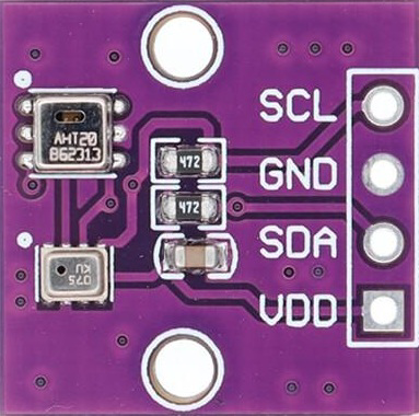
- My Comp is a custom electronic component designed by Arduino, combining the functionality of the AHT20 temperature and humidity sensor with the BMP280 barometric pressure sensor. This hybrid module is tailored for applications requiring precise environmental monitoring, such as weather stations, IoT devices, and industrial automation systems.
- Common use cases include:
- Environmental monitoring and data logging
- Smart home systems
- Altitude measurement for drones and robotics
- HVAC (Heating, Ventilation, and Air Conditioning) systems
Explore Projects Built with My comp
Beelink Mini S12 N95 and Arduino UNO Based Fingerprint Authentication System with ESP32 CAM

This circuit features a Beelink MINI S12 N95 computer connected to a 7-inch display via HDMI for video output and two USB connections for power and touch screen functionality. An Arduino UNO is interfaced with a fingerprint scanner for biometric input. The Beelink MINI S12 N95 is powered by a PC power supply, which in turn is connected to a 240V power source. Additionally, an ESP32 CAM module is powered and programmed via a USB plug and an FTDI programmer, respectively, for wireless camera capabilities.
I2C-Controlled OLED Display with External EEPROM and Interactive Pushbuttons

This is a microcontroller-based interactive device featuring a Wemos D1 Mini, an OLED display, external EEPROM, and an I/O expander. It includes user input buttons and status LEDs, with potential MIDI interface capabilities.
Arduino Mega 2560 Controlled LCD Display with Adjustable Contrast
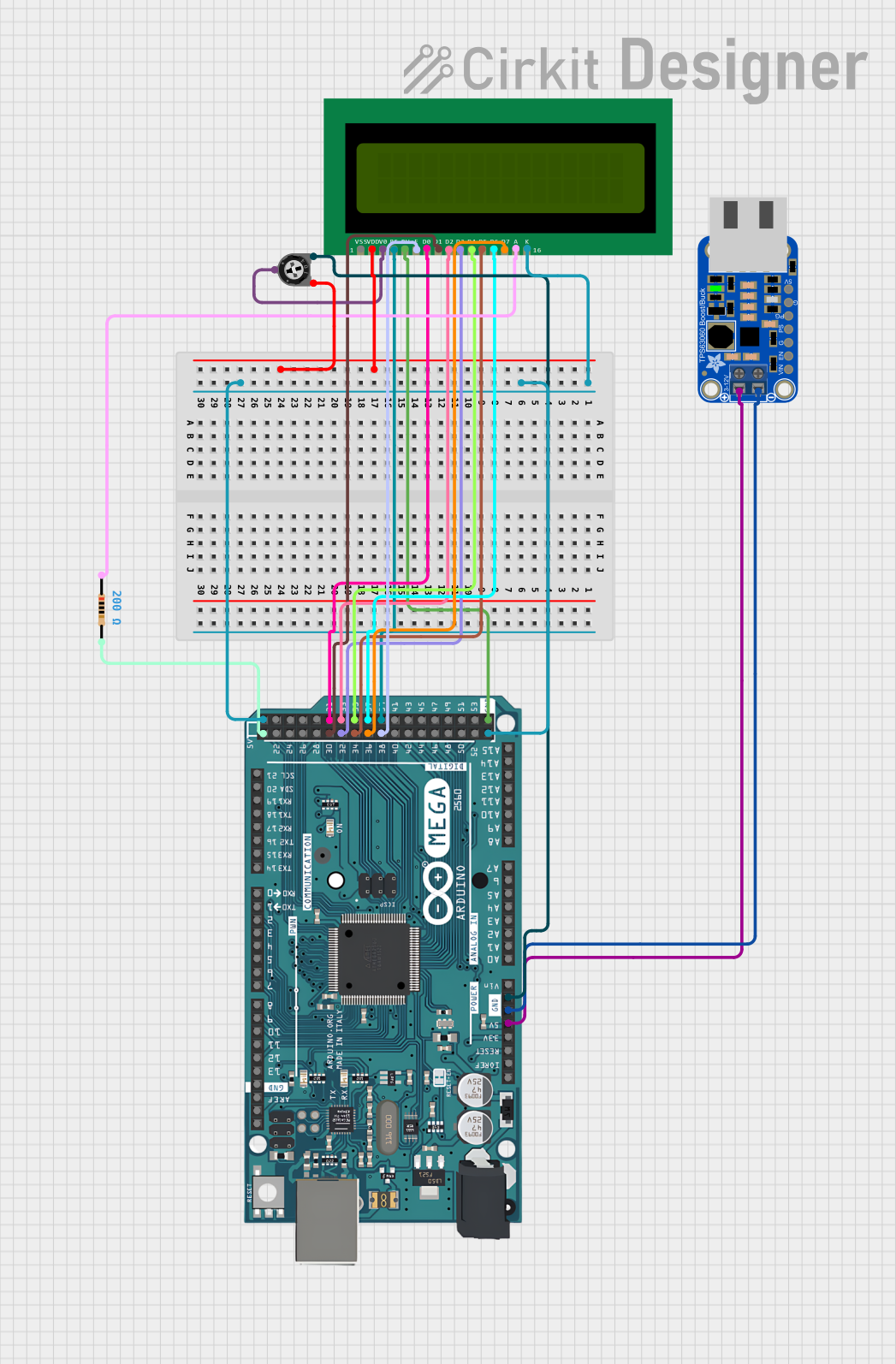
This circuit features an Arduino Mega 2560 microcontroller connected to a 16x2 LCD display, with a trimmer potentiometer to adjust the LCD contrast and a resistor for backlight current limiting. The Arduino is programmed to initialize the LCD and display the message 'Hello, World!'. The circuit is powered through the Arduino's 5V pin, which is connected to a voltage regulator (verter_usb), and is designed for displaying simple text messages with adjustable visibility.
LED Indicator System with Power Stabilizer and Measurement Meters

This circuit is a power distribution and monitoring system that includes multiple LEDs for status indication, a stabilizer module, and measurement instruments such as voltmeters and ammeters. It is designed to supply power to a computer and monitor the power quality and current flow, with protection provided by MCBs (Miniature Circuit Breakers).
Explore Projects Built with My comp
Beelink Mini S12 N95 and Arduino UNO Based Fingerprint Authentication System with ESP32 CAM
This circuit features a Beelink MINI S12 N95 computer connected to a 7-inch display via HDMI for video output and two USB connections for power and touch screen functionality. An Arduino UNO is interfaced with a fingerprint scanner for biometric input. The Beelink MINI S12 N95 is powered by a PC power supply, which in turn is connected to a 240V power source. Additionally, an ESP32 CAM module is powered and programmed via a USB plug and an FTDI programmer, respectively, for wireless camera capabilities.
I2C-Controlled OLED Display with External EEPROM and Interactive Pushbuttons
This is a microcontroller-based interactive device featuring a Wemos D1 Mini, an OLED display, external EEPROM, and an I/O expander. It includes user input buttons and status LEDs, with potential MIDI interface capabilities.
Arduino Mega 2560 Controlled LCD Display with Adjustable Contrast
This circuit features an Arduino Mega 2560 microcontroller connected to a 16x2 LCD display, with a trimmer potentiometer to adjust the LCD contrast and a resistor for backlight current limiting. The Arduino is programmed to initialize the LCD and display the message 'Hello, World!'. The circuit is powered through the Arduino's 5V pin, which is connected to a voltage regulator (verter_usb), and is designed for displaying simple text messages with adjustable visibility.
LED Indicator System with Power Stabilizer and Measurement Meters
This circuit is a power distribution and monitoring system that includes multiple LEDs for status indication, a stabilizer module, and measurement instruments such as voltmeters and ammeters. It is designed to supply power to a computer and monitor the power quality and current flow, with protection provided by MCBs (Miniature Circuit Breakers).
Technical Specifications
Key Technical Details
| Parameter | Value |
|---|---|
| Manufacturer | Arduino |
| Part ID | AHT20+BMP280 |
| Operating Voltage | 3.3V to 5V |
| Communication Protocol | I2C |
| Temperature Range | -40°C to 85°C (AHT20) |
| Humidity Range | 0% to 100% RH (AHT20) |
| Pressure Range | 300 hPa to 1100 hPa (BMP280) |
| Temperature Accuracy | ±0.3°C (AHT20), ±1°C (BMP280) |
| Humidity Accuracy | ±2% RH (AHT20) |
| Pressure Accuracy | ±1 hPa (BMP280) |
| Power Consumption | Low power consumption for battery use |
Pin Configuration and Descriptions
| Pin Name | Description | Notes |
|---|---|---|
| VCC | Power supply (3.3V to 5V) | Connect to the power source |
| GND | Ground | Connect to the circuit ground |
| SDA | I2C Data Line | Connect to Arduino SDA pin |
| SCL | I2C Clock Line | Connect to Arduino SCL pin |
Usage Instructions
How to Use the Component in a Circuit
Wiring the Component:
- Connect the VCC pin to a 3.3V or 5V power source.
- Connect the GND pin to the ground of your circuit.
- Connect the SDA pin to the SDA pin on your Arduino (A4 on Arduino UNO).
- Connect the SCL pin to the SCL pin on your Arduino (A5 on Arduino UNO).
Install Required Libraries:
- Install the
Adafruit_AHTX0andAdafruit_BMP280libraries from the Arduino Library Manager.
- Install the
Upload Example Code:
- Use the following code to read temperature, humidity, and pressure data:
#include <Wire.h>
#include <Adafruit_AHTX0.h> // Library for AHT20 sensor
#include <Adafruit_BMP280.h> // Library for BMP280 sensor

// Create sensor objects
Adafruit_AHTX0 aht;
Adafruit_BMP280 bmp;

void setup() {
  Serial.begin(9600);
  while (!Serial); // Wait for Serial Monitor to open

  // Initialize AHT20 sensor
  if (!aht.begin()) {
    Serial.println("Failed to initialize AHT20 sensor!");
    while (1);
  }
  Serial.println("AHT20 sensor initialized.");

  // Initialize BMP280 sensor
  if (!bmp.begin(0x76)) { // Default I2C address for BMP280
    Serial.println("Failed to initialize BMP280 sensor!");
    while (1);
  }
  Serial.println("BMP280 sensor initialized.");
}

void loop() {
  // Read data from AHT20
  sensors_event_t humidity, temp;
  aht.getEvent(&humidity, &temp);

  // Read data from BMP280
  float pressure = bmp.readPressure() / 100.0F; // Convert to hPa

  // Print sensor data
  Serial.print("Temperature (AHT20): ");
  Serial.print(temp.temperature);
  Serial.println(" °C");

  Serial.print("Humidity (AHT20): ");
  Serial.print(humidity.relative_humidity);
  Serial.println(" %");

  Serial.print("Pressure (BMP280): ");
  Serial.print(pressure);
  Serial.println(" hPa");

  delay(2000); // Wait 2 seconds before next reading
}
Important Considerations and Best Practices
- Ensure proper pull-up resistors (typically 4.7kΩ) are connected to the SDA and SCL lines if not already included on the module.
- Avoid placing the sensor in direct sunlight or near heat sources to ensure accurate readings.
- Use a decoupling capacitor (e.g., 0.1µF) between VCC and GND to reduce noise in the power supply.
Troubleshooting and FAQs
Common Issues and Solutions
Sensor Not Detected:
- Ensure the wiring is correct and matches the pin configuration.
- Verify that the I2C address (default: 0x76 for BMP280) is correct in the code.
Inaccurate Readings:
- Check for environmental factors like condensation or dust on the sensor.
- Calibrate the sensor if necessary using reference equipment.
Arduino Freezes or Crashes:
- Ensure the power supply is stable and sufficient for the Arduino and sensors.
- Check for loose connections or short circuits.
FAQs
Can I use this module with a 3.3V microcontroller? Yes, the module supports both 3.3V and 5V logic levels.
What is the maximum cable length for I2C communication? The maximum length depends on the pull-up resistor values and operating frequency, but typically it is recommended to keep it under 1 meter for reliable communication.
Can I use this module outdoors? While the sensors can operate outdoors, they should be protected from direct exposure to water, dust, and extreme conditions.
This concludes the documentation for the My Comp module.