How to Use ESP32-WROVER-IE (38pin): Examples, Pinouts, and Specs
Introduction
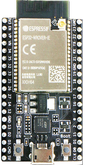
The ESP32-WROVER-IE (38pin) is a powerful Wi-Fi and Bluetooth microcontroller module designed for high-performance IoT applications. It features a dual-core processor, integrated memory, and support for a wide range of peripherals, making it suitable for tasks such as wireless communication, data processing, and sensor integration. Its compact design and robust capabilities make it a popular choice for developers building smart devices, home automation systems, and industrial IoT solutions.
Explore Projects Built with ESP32-WROVER-IE (38pin)


Explore Projects Built with ESP32-WROVER-IE (38pin)
Common Applications and Use Cases
- Smart home devices (e.g., smart lights, thermostats)
- Industrial IoT systems (e.g., remote monitoring, predictive maintenance)
- Wearable technology
- Wireless sensor networks
- Robotics and automation
- Prototyping and development of IoT projects
Technical Specifications
The ESP32-WROVER-IE (38pin) module is packed with advanced features and specifications:
Key Technical Details
- Processor: Dual-core Xtensa® 32-bit LX6 CPU, up to 240 MHz
- Wireless Connectivity:
- Wi-Fi: 802.11 b/g/n
- Bluetooth: v4.2 BR/EDR and BLE
- Memory:
- 4 MB PSRAM
- 4 MB Flash
- Operating Voltage: 3.3V
- GPIO Pins: 34 (configurable for various functions)
- Interfaces:
- SPI, I2C, I2S, UART, PWM, ADC, DAC
- Operating Temperature: -40°C to +85°C
- Dimensions: 18 mm x 31.4 mm
Pin Configuration and Descriptions
The ESP32-WROVER-IE (38pin) module has 38 pins, each with specific functions. Below is the pinout description:
| Pin Number | Pin Name | Function |
|---|---|---|
| 1 | GND | Ground |
| 2 | 3V3 | 3.3V Power Supply |
| 3 | EN | Enable (Active High) |
| 4 | IO36 | ADC1_CH0, VP (Analog Input) |
| 5 | IO39 | ADC1_CH3, VN (Analog Input) |
| 6 | IO34 | ADC1_CH6 (Analog Input) |
| 7 | IO35 | ADC1_CH7 (Analog Input) |
| 8 | IO32 | ADC1_CH4, Touch9 |
| 9 | IO33 | ADC1_CH5, Touch8 |
| 10 | IO25 | DAC1, ADC2_CH8 |
| 11 | IO26 | DAC2, ADC2_CH9 |
| 12 | IO27 | ADC2_CH7, Touch7 |
| 13 | IO14 | ADC2_CH6, Touch6, HSPI_CLK |
| 14 | IO12 | ADC2_CH5, Touch5, HSPI_MISO |
| 15 | IO13 | ADC2_CH4, Touch4, HSPI_MOSI |
| 16 | IO15 | ADC2_CH3, Touch3, HSPI_CS |
| 17 | IO2 | ADC2_CH2, Touch2 |
| 18 | IO0 | ADC2_CH1, Touch1 |
| 19 | IO4 | ADC2_CH0, Touch0 |
| 20 | IO16 | UART2_RX |
| 21 | IO17 | UART2_TX |
| 22 | IO5 | GPIO5 |
| 23 | IO18 | VSPI_CLK |
| 24 | IO19 | VSPI_MISO |
| 25 | IO21 | I2C SDA |
| 26 | IO22 | I2C SCL |
| 27 | IO23 | VSPI_MOSI |
| 28 | IO36 | ADC1_CH0 |
| 29 | IO39 | ADC1_CH3 |
| 30 | IO34 | ADC1_CH6 |
| 31 | IO35 | ADC1_CH7 |
| 32 | IO32 | ADC1_CH4 |
| 33 | IO33 | ADC1_CH5 |
| 34 | IO25 | DAC1 |
| 35 | IO26 | DAC2 |
| 36 | IO27 | GPIO27 |
| 37 | IO14 | GPIO14 |
| 38 | IO12 | GPIO12 |
Usage Instructions
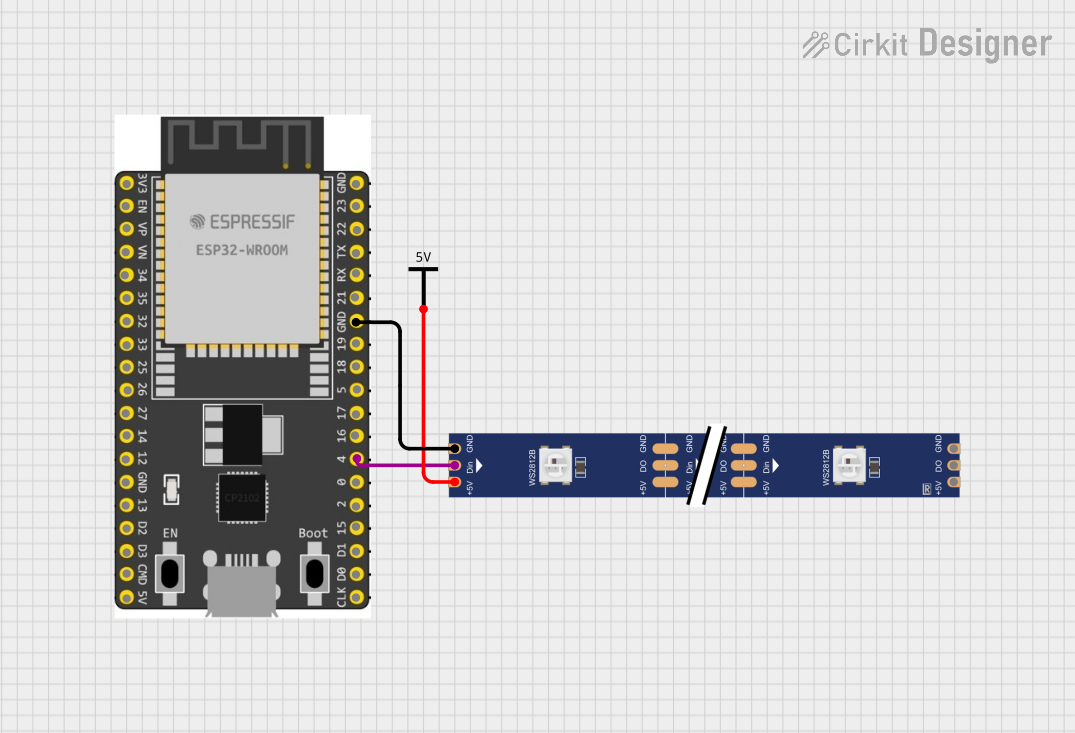
How to Use the ESP32-WROVER-IE in a Circuit
- Power Supply: Connect the 3.3V pin to a stable 3.3V power source and GND to ground.
- Programming: Use a USB-to-serial adapter to connect the module to your computer. Ensure the EN pin is pulled high to enable the module.
- GPIO Configuration: Configure the GPIO pins as needed for your application (e.g., input, output, ADC, PWM).
- Peripherals: Connect external devices (e.g., sensors, actuators) to the appropriate pins based on their communication protocol (SPI, I2C, UART, etc.).
Important Considerations and Best Practices
- Voltage Levels: Ensure all connected devices operate at 3.3V logic levels to avoid damaging the module.
- Antenna Placement: Keep the onboard antenna area clear of metal objects to ensure optimal wireless performance.
- Power Supply Stability: Use a decoupling capacitor (e.g., 10 µF) near the power pins to stabilize the power supply.
- Boot Mode: To enter bootloader mode for programming, hold the IO0 pin low while resetting the module.
Example Code for Arduino UNO
The ESP32-WROVER-IE can be programmed using the Arduino IDE. Below is an example of a basic Wi-Fi connection:
#include <WiFi.h> // Include the Wi-Fi library

const char* ssid = "Your_SSID";       // Replace with your Wi-Fi SSID
const char* password = "Your_Password"; // Replace with your Wi-Fi password

void setup() {
  Serial.begin(115200); // Initialize serial communication
  WiFi.begin(ssid, password); // Start Wi-Fi connection

  Serial.print("Connecting to Wi-Fi");
  while (WiFi.status() != WL_CONNECTED) {
    delay(500);
    Serial.print("."); // Print dots while connecting
  }

  Serial.println("\nConnected to Wi-Fi!");
  Serial.print("IP Address: ");
  Serial.println(WiFi.localIP()); // Print the assigned IP address
}

void loop() {
  // Add your main code here
}
Troubleshooting and FAQs
Common Issues and Solutions
- Wi-Fi Connection Fails:
- Solution: Double-check the SSID and password. Ensure the router is powered on and within range.
- Module Not Detected by Computer:
- Solution: Verify the USB-to-serial adapter is properly connected. Install the correct USB driver for your adapter.
- GPIO Pins Not Responding:
- Solution: Ensure the pins are correctly configured in your code. Check for short circuits or incorrect wiring.
- Overheating:
- Solution: Verify the power supply voltage is 3.3V. Avoid overloading the module with excessive current.
FAQs
Q: Can the ESP32-WROVER-IE operate on 5V?
A: No, the module operates at 3.3V. Use a voltage regulator if your power source is 5V.Q: How do I reset the module?
A: Pull the EN pin low momentarily or press the reset button (if available).Q: Can I use the ESP32-WROVER-IE with Arduino libraries?
A: Yes, the module is compatible with the Arduino IDE and supports many libraries.Q: What is the maximum range of the Wi-Fi?
A: The range depends on environmental factors but typically reaches up to 100 meters in open space.
This documentation provides a comprehensive guide to using the ESP32-WROVER-IE (38pin) module effectively.