How to Use Main Relay Box: Examples, Pinouts, and Specs
Introduction
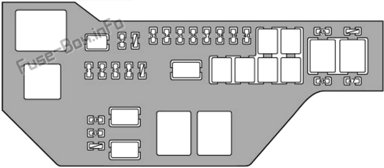
The Main Relay Box by Toyota is a central unit designed to house multiple relays, enabling the control of high-power devices or circuits. It acts as an intermediary between low-power control signals and high-power systems, ensuring efficient and safe operation. This component is commonly used in automotive applications, industrial machinery, and other systems requiring reliable relay-based switching.
Explore Projects Built with Main Relay Box


Explore Projects Built with Main Relay Box
Common Applications and Use Cases
- Automotive systems (e.g., controlling headlights, fuel pumps, and cooling fans)
- Industrial equipment requiring high-power switching
- Home automation systems
- Power distribution in complex circuits
- Safety-critical systems where isolation between control and power circuits is essential
Technical Specifications
Key Technical Details
| Parameter | Value/Description |
|---|---|
| Manufacturer | Toyota |
| Part ID | Main Relay Box |
| Operating Voltage Range | 12V DC (typical automotive systems) |
| Maximum Current Rating | 30A per relay (varies by relay type) |
| Number of Relays | 4 to 8 (depending on the specific model) |
| Relay Type | Electromechanical relays |
| Operating Temperature | -40°C to +85°C |
| Dimensions | Varies by model; typically compact for automotive use |
| Mounting Style | Bolt-on or snap-in |
Pin Configuration and Descriptions
The Main Relay Box contains multiple relays, each with its own pin configuration. Below is a general description of the pin layout for a single relay within the box:
| Pin Number | Pin Name | Description |
|---|---|---|
| 1 | Coil Positive | Connects to the positive terminal of the control voltage. |
| 2 | Coil Negative | Connects to the negative terminal (ground). |
| 3 | Common (COM) | Common terminal for the relay's switching circuit. |
| 4 | Normally Open (NO) | Open circuit when the relay is inactive; closes when activated. |
| 5 | Normally Closed (NC) | Closed circuit when the relay is inactive; opens when activated. |
Note: The exact pin configuration may vary depending on the specific relay model used within the Main Relay Box. Always refer to the datasheet for precise details.
Usage Instructions
How to Use the Main Relay Box in a Circuit
- Power Supply Connection: Ensure the Main Relay Box is connected to a stable 12V DC power source. Verify the voltage and current ratings of the connected devices to avoid overloading.
- Control Signal Wiring: Connect the control signals (e.g., from a microcontroller or switch) to the relay coil pins. Use appropriate resistors or diodes if required to protect the control circuit.
- Load Connection: Connect the high-power devices (e.g., motors, lights) to the relay's COM, NO, and NC terminals as per the desired switching configuration.
- Grounding: Ensure proper grounding of the Main Relay Box to prevent electrical noise and ensure safe operation.
- Testing: Before full operation, test the circuit with a multimeter to confirm proper connections and functionality.
Important Considerations and Best Practices
- Current Ratings: Do not exceed the maximum current rating of 30A per relay. Use external relays or contactors for higher loads.
- Flyback Diodes: Install flyback diodes across the relay coils to protect the control circuit from voltage spikes during switching.
- Heat Management: Ensure adequate ventilation or cooling to prevent overheating during prolonged operation.
- Secure Mounting: Properly mount the Main Relay Box to avoid vibrations or loose connections, especially in automotive applications.
Example: Connecting the Main Relay Box to an Arduino UNO
Below is an example of how to control a relay in the Main Relay Box using an Arduino UNO:
// Example: Controlling a relay in the Main Relay Box with Arduino UNO

const int relayPin = 7; // Pin connected to the relay's control input

void setup() {
  pinMode(relayPin, OUTPUT); // Set the relay pin as an output
  digitalWrite(relayPin, LOW); // Ensure the relay is off initially
}

void loop() {
  digitalWrite(relayPin, HIGH); // Turn the relay on
  delay(1000); // Keep it on for 1 second
  digitalWrite(relayPin, LOW); // Turn the relay off
  delay(1000); // Keep it off for 1 second
}
Note: Use a transistor or relay driver circuit between the Arduino and the relay coil to handle the current requirements safely.
Troubleshooting and FAQs
Common Issues and Solutions
| Issue | Possible Cause | Solution |
|---|---|---|
| Relay not switching | Insufficient control voltage or current | Verify the control signal voltage and current. Use a driver circuit if needed. |
| Overheating of the relay box | Exceeding current rating or poor ventilation | Reduce the load or improve cooling/ventilation. |
| Noise or erratic behavior | Electrical noise or poor grounding | Ensure proper grounding and use decoupling capacitors if necessary. |
| Burnt relay contacts | High inrush current or arcing | Use relays with higher ratings or add snubber circuits. |
FAQs
Can the Main Relay Box handle AC loads?
- Yes, but ensure the relays are rated for AC operation and the load does not exceed the specified ratings.
How do I replace a faulty relay in the box?
- Disconnect the power supply, open the relay box, and carefully remove the faulty relay. Replace it with a compatible relay of the same specifications.
Can I use the Main Relay Box with a 24V system?
- No, the Main Relay Box is designed for 12V systems. Using it with a 24V system may damage the relays or cause malfunction.
What precautions should I take when using the Main Relay Box in an automotive application?
- Ensure secure mounting, proper grounding, and protection against moisture and vibrations.
By following this documentation, users can effectively integrate the Toyota Main Relay Box into their projects, ensuring reliable and efficient operation.