How to Use POWER DISTRIBUTION FRAME: Examples, Pinouts, and Specs
Introduction
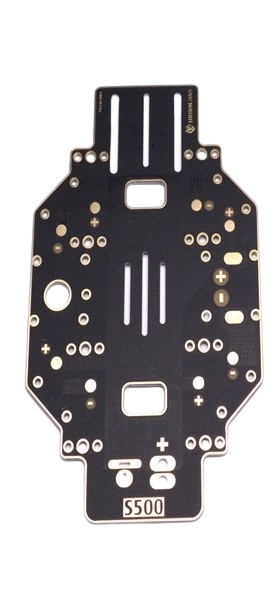
The Power Distribution Frame (Manufacturer: S500, Part ID: Drone Frame) is a structural component designed to organize and distribute electrical power efficiently and safely across multiple circuits or devices. It is commonly used in systems requiring centralized power management, such as drones, robotics, and other electronic systems. By consolidating power distribution, it reduces wiring complexity and ensures stable power delivery to connected components.
Explore Projects Built with POWER DISTRIBUTION FRAME


Explore Projects Built with POWER DISTRIBUTION FRAME
Common Applications and Use Cases
- Drones: Distributes power from a central battery to motors, flight controllers, and other peripherals.
- Robotics: Supplies power to actuators, sensors, and control boards.
- Embedded Systems: Manages power for multiple modules in compact electronic designs.
- Prototyping: Simplifies power distribution in experimental setups.
Technical Specifications
The following table outlines the key technical details of the S500 Power Distribution Frame:
| Parameter | Specification |
|---|---|
| Manufacturer | S500 |
| Part ID | Drone Frame |
| Input Voltage Range | 7V - 26V |
| Maximum Current Rating | 90A (total) |
| Output Voltage | Matches input voltage (unregulated) |
| Number of Output Ports | 4 main outputs, 2 auxiliary outputs |
| Dimensions | 100mm x 100mm x 3mm |
| Weight | 25g |
| Material | PCB with copper traces |
| Mounting Holes | 4 holes (compatible with 250-500mm drone frames) |
Pin Configuration and Descriptions
The S500 Power Distribution Frame features multiple connection points for input and output. Below is a detailed description:
| Pin/Port | Description |
|---|---|
| Input (+) | Positive terminal for connecting the main power source (e.g., LiPo battery). |
| Input (-) | Negative terminal for connecting the main power source. |
| Output 1 (+/-) | Power output for motor 1 or other devices. |
| Output 2 (+/-) | Power output for motor 2 or other devices. |
| Output 3 (+/-) | Power output for motor 3 or other devices. |
| Output 4 (+/-) | Power output for motor 4 or other devices. |
| Auxiliary 1 (+/-) | Auxiliary power output for additional peripherals (e.g., LEDs, cameras). |
| Auxiliary 2 (+/-) | Auxiliary power output for additional peripherals. |
Usage Instructions
How to Use the Component in a Circuit
- Mounting the Frame: Secure the S500 Power Distribution Frame to your drone or system using the provided mounting holes. Ensure it is firmly attached to avoid vibrations or movement.
- Connecting the Power Source:
- Connect the positive terminal of your power source (e.g., LiPo battery) to the
Input (+)pin. - Connect the negative terminal of your power source to the
Input (-)pin.
- Connect the positive terminal of your power source (e.g., LiPo battery) to the
- Connecting Devices:
- Attach the positive and negative wires of each device (e.g., motors, controllers) to the corresponding output ports.
- Use the auxiliary outputs for low-power peripherals like LEDs or cameras.
- Verify Connections: Double-check all connections to ensure proper polarity and secure wiring.
- Power On: Once all connections are verified, power on the system and monitor for any irregularities.
Important Considerations and Best Practices
- Voltage Compatibility: Ensure that all connected devices are compatible with the input voltage range (7V - 26V).
- Current Limits: Do not exceed the maximum current rating of 90A to prevent overheating or damage.
- Wire Gauge: Use appropriate wire gauges for high-current connections to minimize resistance and heat.
- Short Circuit Protection: Add fuses or circuit breakers to protect the system from short circuits.
- Heat Dissipation: Avoid placing the frame in enclosed spaces without ventilation, as high currents can generate heat.
Example: Connecting to an Arduino UNO
If you are using the S500 Power Distribution Frame to power an Arduino UNO and peripherals, follow these steps:
- Connect the power source to the input terminals of the frame.
- Use one of the auxiliary outputs to supply 5V to the Arduino UNO's
VINpin (if using a voltage regulator) or directly to the5Vpin (if the input voltage is regulated). - Connect the ground (
GND) of the auxiliary output to the Arduino'sGNDpin.
Here is an example Arduino code to control a motor connected to the frame:
// Example code to control a motor using Arduino UNO
const int motorPin = 9; // PWM pin connected to motor driver

void setup() {
  pinMode(motorPin, OUTPUT); // Set motor pin as output
}

void loop() {
  analogWrite(motorPin, 128); // Set motor speed to 50% (PWM value: 128)
  delay(2000); // Run motor for 2 seconds
  analogWrite(motorPin, 0); // Stop motor
  delay(2000); // Wait for 2 seconds
}
Troubleshooting and FAQs
Common Issues Users Might Face
No Power to Devices:
- Cause: Loose or incorrect connections.
- Solution: Verify all connections and ensure proper polarity.
Overheating:
- Cause: Exceeding the maximum current rating or poor ventilation.
- Solution: Reduce the load or improve airflow around the frame.
Short Circuit:
- Cause: Exposed wires or incorrect wiring.
- Solution: Inspect and insulate all connections. Use fuses for added protection.
Voltage Drop:
- Cause: Using thin wires for high-current connections.
- Solution: Use thicker wires to reduce resistance.
FAQs
Can I use the frame with a 6S LiPo battery?
- Yes, the frame supports up to 26V, which is compatible with a 6S LiPo battery.
Is the frame compatible with brushless motors?
- Yes, it is designed to distribute power to brushless motors commonly used in drones.
Can I use the auxiliary outputs for a 5V device?
- Only if the input voltage matches the device's requirements or if a voltage regulator is used.
What is the maximum power the frame can handle?
- The frame can handle up to 90A total current, which translates to a maximum power of approximately 2340W at 26V.
By following this documentation, users can effectively integrate the S500 Power Distribution Frame into their systems for efficient and reliable power management.