Cirkit Designer Logo
Cirkit Designer
Your all-in-one circuit design IDE
Home / 
Component Documentation

How to Use PhotoDiode sensor: Examples, Pinouts, and Specs

Image of PhotoDiode sensor
Cirkit Designer LogoDesign with PhotoDiode sensor in Cirkit Designer

Introduction

A photodiode sensor is a semiconductor device that converts light into an electrical current. The current generated is proportional to the intensity of the light falling on the photodiode. This component is widely used in optical applications, light detection systems, and as a key element in devices such as light meters, optical communication systems, and safety equipment.

Explore Projects Built with PhotoDiode sensor

Use Cirkit Designer to design, explore, and prototype these projects online. Some projects support real-time simulation. Click "Open Project" to start designing instantly!
Arduino Nano-Based Light Sensing Circuit with LED Indicator
Image of Copy of LED yellow 2 pin mood light: A project utilizing PhotoDiode sensor in a practical application
This circuit is designed to measure light intensity using a photodiode and a resistor to create a voltage divider, with the signal read by the Arduino Nano's A0 pin. A yellow LED is connected to the D2 pin, potentially serving as an indicator. The 9V battery powers the circuit, and the Arduino's code is yet to be implemented for specific functionality.
Cirkit Designer LogoOpen Project in Cirkit Designer
Arduino Nano-Based Light Intensity Data Logger with Op-Amp Signal Conditioning
Image of TEST: A project utilizing PhotoDiode sensor in a practical application
This circuit is designed to detect light intensity using a photodiode and convert the signal into a readable voltage using a Transimpedance Amplifier (TIA) configuration with an LM358 Op-Amp. The resistor and capacitor form a feedback network for the TIA, which outputs a voltage proportional to the light intensity to the Arduino Nano's analog input (A0). The Arduino Nano is programmed to read this analog voltage, convert it to a digital value, and output the result over serial communication for monitoring or further processing.
Cirkit Designer LogoOpen Project in Cirkit Designer
Arduino Nano-Based Light and Motion Sensing System
Image of Motion deductor  using PIR sensor : A project utilizing PhotoDiode sensor in a practical application
This circuit is designed to monitor environmental conditions using a PIR sensor for motion detection and a photocell for light level measurement. The Arduino Nano processes these inputs and drives an LED as an output indicator. The resistor is used in conjunction with the photocell to create a voltage divider for analog input to the Arduino.
Cirkit Designer LogoOpen Project in Cirkit Designer
Arduino UNO-Based Light-Sensitive LED Controller
Image of Led_sensoreLuce: A project utilizing PhotoDiode sensor in a practical application
This circuit is designed to detect light levels using a photodiode and control an LED based on the detected light. The Arduino UNO reads the voltage across the photodiode connected to its analog pin A0 and turns on the LED connected to digital pin D3 through a 220 Ohm resistor if the light level falls below a predefined threshold. The photodiode is powered by the Arduino's 5V output, and the LED's current is limited by the resistor.
Cirkit Designer LogoOpen Project in Cirkit Designer

Explore Projects Built with PhotoDiode sensor

Use Cirkit Designer to design, explore, and prototype these projects online. Some projects support real-time simulation. Click "Open Project" to start designing instantly!
Image of Copy of LED yellow 2 pin mood light: A project utilizing PhotoDiode sensor in a practical application
Arduino Nano-Based Light Sensing Circuit with LED Indicator
This circuit is designed to measure light intensity using a photodiode and a resistor to create a voltage divider, with the signal read by the Arduino Nano's A0 pin. A yellow LED is connected to the D2 pin, potentially serving as an indicator. The 9V battery powers the circuit, and the Arduino's code is yet to be implemented for specific functionality.
Cirkit Designer LogoOpen Project in Cirkit Designer
Image of TEST: A project utilizing PhotoDiode sensor in a practical application
Arduino Nano-Based Light Intensity Data Logger with Op-Amp Signal Conditioning
This circuit is designed to detect light intensity using a photodiode and convert the signal into a readable voltage using a Transimpedance Amplifier (TIA) configuration with an LM358 Op-Amp. The resistor and capacitor form a feedback network for the TIA, which outputs a voltage proportional to the light intensity to the Arduino Nano's analog input (A0). The Arduino Nano is programmed to read this analog voltage, convert it to a digital value, and output the result over serial communication for monitoring or further processing.
Cirkit Designer LogoOpen Project in Cirkit Designer
Image of Motion deductor  using PIR sensor : A project utilizing PhotoDiode sensor in a practical application
Arduino Nano-Based Light and Motion Sensing System
This circuit is designed to monitor environmental conditions using a PIR sensor for motion detection and a photocell for light level measurement. The Arduino Nano processes these inputs and drives an LED as an output indicator. The resistor is used in conjunction with the photocell to create a voltage divider for analog input to the Arduino.
Cirkit Designer LogoOpen Project in Cirkit Designer
Image of Led_sensoreLuce: A project utilizing PhotoDiode sensor in a practical application
Arduino UNO-Based Light-Sensitive LED Controller
This circuit is designed to detect light levels using a photodiode and control an LED based on the detected light. The Arduino UNO reads the voltage across the photodiode connected to its analog pin A0 and turns on the LED connected to digital pin D3 through a 220 Ohm resistor if the light level falls below a predefined threshold. The photodiode is powered by the Arduino's 5V output, and the LED's current is limited by the resistor.
Cirkit Designer LogoOpen Project in Cirkit Designer

Common Applications and Use Cases

  • Light intensity measurement
  • Optical communication systems
  • Infrared (IR) detection
  • Proximity sensors
  • Safety and security systems (e.g., smoke detectors)
  • Solar energy monitoring

Technical Specifications

Below are the general technical specifications for a typical photodiode sensor. Note that specific values may vary depending on the manufacturer and model.

Parameter Value
Operating Voltage 0 to 30 V (reverse bias)
Wavelength Sensitivity 400 nm to 1100 nm (visible to IR)
Dark Current 1 nA to 10 nA (typical)
Response Time 10 ns to 1 µs
Reverse Breakdown Voltage 30 V (typical)
Package Type Through-hole or SMD

Pin Configuration and Descriptions

The photodiode sensor typically has two pins: an anode and a cathode. Below is the pin configuration:

Pin Description
Anode Positive terminal; connects to the positive side of the circuit.
Cathode Negative terminal; connects to the negative side or ground.

Usage Instructions

How to Use the Component in a Circuit

  1. Basic Connection:

    • Connect the cathode to the negative terminal of the power supply or ground.
    • Connect the anode to the positive terminal of the circuit, typically through a resistor to limit current.
    • For reverse bias operation (common in photodiodes), connect the cathode to the positive voltage and the anode to ground.
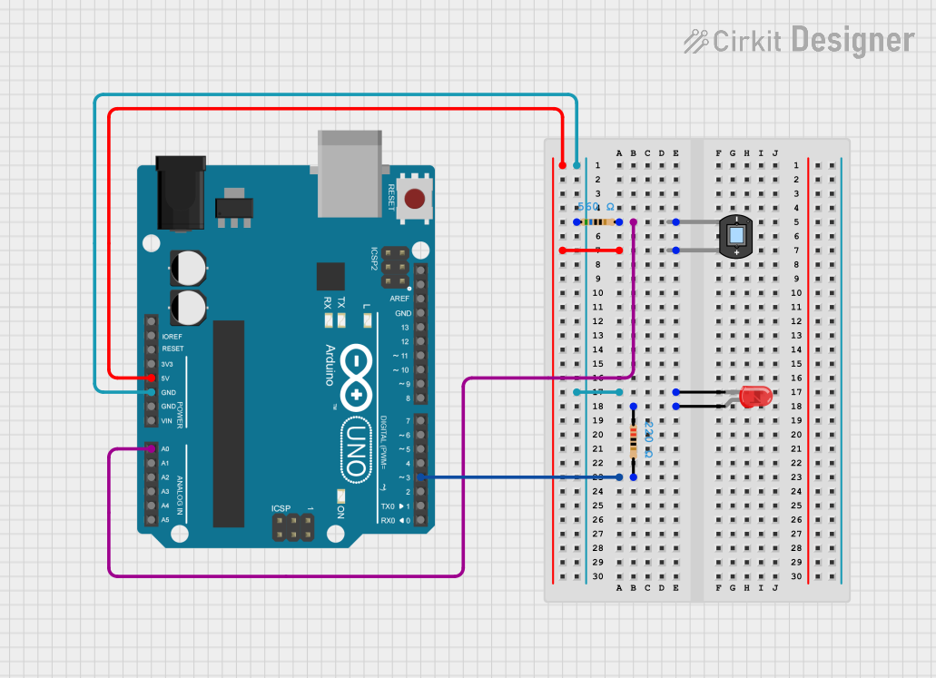
  2. Interfacing with a Microcontroller (e.g., Arduino UNO):

    • Use a pull-down resistor (e.g., 10 kΩ) to stabilize the output signal.
    • Connect the photodiode in reverse bias mode for better sensitivity.
    • Use an analog input pin on the Arduino to read the voltage across the photodiode.
  3. Amplification:

    • If the output current is too small, use an operational amplifier (op-amp) in a transimpedance configuration to convert the current to a measurable voltage.

Important Considerations and Best Practices

  • Light Sensitivity: Ensure the photodiode is exposed to the correct wavelength range for your application.
  • Reverse Bias: Operating the photodiode in reverse bias improves response time and sensitivity.
  • Ambient Light: Minimize interference from ambient light by using an optical filter or housing.
  • Temperature Effects: Be aware that temperature changes can affect the photodiode's performance.
  • Resistor Selection: Choose an appropriate resistor value to balance sensitivity and response time.

Example Code for Arduino UNO

Below is an example of how to use a photodiode sensor with an Arduino UNO to measure light intensity:

// Photodiode Sensor Example with Arduino UNO
// Reads light intensity and outputs the value to the Serial Monitor

const int photoDiodePin = A0; // Analog pin connected to the photodiode
int lightIntensity = 0;      // Variable to store the light intensity value

void setup() {
  Serial.begin(9600); // Initialize serial communication at 9600 baud
  pinMode(photoDiodePin, INPUT); // Set the photodiode pin as input
}

void loop() {
  // Read the analog value from the photodiode
  lightIntensity = analogRead(photoDiodePin);

  // Print the light intensity value to the Serial Monitor
  Serial.print("Light Intensity: ");
  Serial.println(lightIntensity);

  delay(500); // Wait for 500 milliseconds before the next reading
}

Troubleshooting and FAQs

Common Issues and Solutions

  1. No Output Signal:

    • Cause: Incorrect wiring or insufficient light.
    • Solution: Verify the connections and ensure the photodiode is exposed to light.
  2. Low Sensitivity:

    • Cause: Incorrect resistor value or improper biasing.
    • Solution: Adjust the resistor value or ensure the photodiode is in reverse bias.
  3. Fluctuating Readings:

    • Cause: Ambient light interference or electrical noise.
    • Solution: Use an optical filter or shield the photodiode from ambient light. Add a capacitor across the photodiode to reduce noise.
  4. Slow Response Time:

    • Cause: High capacitance or incorrect circuit design.
    • Solution: Use a lower-value resistor or optimize the circuit for faster response.

FAQs

Q1: Can I use a photodiode without reverse bias?
A1: Yes, but the response time and sensitivity will be lower. Reverse bias is recommended for most applications.

Q2: How do I select the right photodiode for my application?
A2: Consider factors such as wavelength sensitivity, response time, and package type based on your specific requirements.

Q3: Can a photodiode detect infrared light?
A3: Yes, most photodiodes are sensitive to infrared light, typically up to 1100 nm.

Q4: Why is my photodiode output very weak?
A4: Photodiodes generate small currents. Use an op-amp in a transimpedance configuration to amplify the signal.

By following this documentation, you can effectively integrate a photodiode sensor into your projects and troubleshoot common issues.